


Mounting and Wiring
Signal Wiring
32 UMC800 Controller Installation and User Guide Release F
4/01
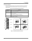
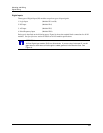
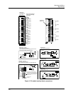
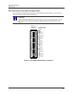
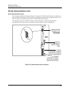
Pulse input/frequency input module with digital outputs
Figure 19 shows the terminal block connections for Pulse/Frequency Input Module. See Specifications
section for details on all I/O module specifications.
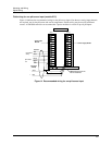
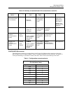
ATTENTION
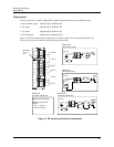
16 Point Digital Input module (ID D) has 32 terminals. If you are using 2 wires per DI, use 22
gage wires so all 32 wires can fit through the rubber grommet in the controller case. See
Figure 19.
32
30
28
26
24
22
20
18
16
14
12
10
8
6
4
2
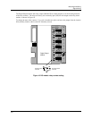
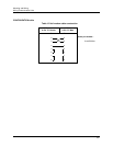
Module ID - D
Identifiable by
32 screws
Each odd-numbered
terminal is internally
grounded.
Input 4 -
Input 4 +
DO3 -
Input 3 -
Input 3 +
DO4 -
DO4 +
DO3 +
DO2 -
DO2 +
DO1 -
DO1 +
Input 2 -
Input 2 +
Input 1 -
Input 1 +
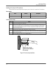
+
Gnd
Figure 19 PI/FI module terminal block connections