


Maintenance
Overview
Release F UMC800 Controller Installation and User Guide 63
4/01
Maintenance
Overview
This section covers procedures in the maintenance, calibration and replacement of the controller and its
components.
Maintenance to the controller consists of the following procedures:
• Routine maintenance
• Calibration of I/O modules. (The backplane is factory calibrated only.)
• Field replacement of controller components
Warranty
• Warranty repair is by board replacement.
• Non-warranty service provides for field repair at the board level with option to return to factory for
repair.
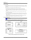
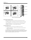
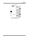
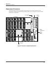
Servicing
The power supply, CPU, and all I/O modules plug into the backplane for easy removal and replacement.
The I/O modules can be replaced without removal of the field wiring from the terminal screws.
The battery is accessible for easy replacement while the controller file is powered and operational to
prevent loss of configuration data.
CAUTION
TO PRESERVE THE CONTROLLER CONFIGURATION PRIOR TO PERFORMING ANY
REPLACEMENT PROCEDURES OR REMOVING POWER TO THE CONTROLLER:
• Be certain that the LoBatt LED is OFF. (MEMORY – LOW BATTERY diagnostic is not
active.)
• Force a cold start of the controller by setting the manual mode switch on the controller to
PROGRAM and then to RUN and allow the controller to complete its start up sequence.
Controller configuration files will be backed up to the flash PROM on the CPU
WARNING – SHOCK HAZARD
Troubleshooting may require access to hazardous live circuits, and should only be
performed by qualified service personnel. More than one switch may be required to de-
energize unit before servicing.