


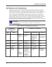

Diagnostics and Troubleshooting
Controller Diagnostics
80 UMC800 Controller Installation and User Guide Release F
4/01
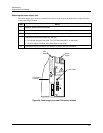
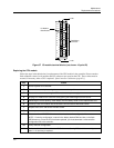
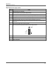
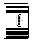
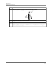
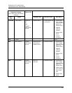
Controller status LEDs
Status indicators on the controller consist of four LEDs that indicate good and fault conditions in the
controller. These LEDs indicate controller status and help to aid troubleshooting when the operator
interface is not nearby or when the controller is not communicating with the operator interface or PC.
Table 19 describes the LEDs and the possible states with their meaning. Refer also to Table 20 and Table
21 for further details on the meaning of the status LEDs.
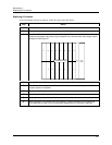
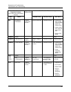
Table 19 Controller status LEDs
Status LED State Meaning
POWER
Steady on Power is applied to the controller backplane.
Blinking Diagnostic indication.
See Table 20 for the details of the indications and their
meaning.
LoBAT
On The CPU battery is low and needs replacement.
FORCE
On
One or more function block output values have been
forced.
RUN
On Controller is in Run mode.
Blinking Controller is in Offline mode
Off Controller is in Program mode.
OR
If POWER LED is blinking a fault has been detected in
controller. See Table 20 for details of the indications and
their meaning.
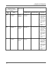
Diagnostic displays
Controller diagnostic summary
Status information, which indicates normal and/or fault conditions in the controller as a result of diagnostic
routines, is accessed through either the operator interface or the user utility program.
• Using the operator interface – the DIAGNOSTIC SUMMARY display lists various controller
components and their current status.
• Using the user utility program – the Controller Diagnostic Summary window provides a more extensive
list of controller parameters and communications status.
I/O module diagnostics
Another status display (or window), I/O Module Diagnostics, shows the status of each of the 16 I/O module
slots in the controller. Each module slot is listed along with the status of the module in that slot.
Table 20 gives the details of the messages shown in the Controller Diagnostic Summary and Table 21
describes I/O Module Diagnostics messages that may appear in each field.