


Maintenance
Replacement Procedures
70 UMC800 Controller Installation and User Guide Release F
4/01
Replacement Procedures
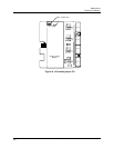
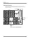
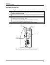
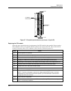
The following tables outline the procedures for replacement of the controller components. Field
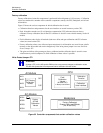
replacement is limited to the Printed Wiring Assembly (PWA) level. Use Figure 35 to locate controller
components for replacement.
12
11
10
9
8
7
6
5
4
3
2
1
12
11
10
9
8
7
6
5
4
3
2
1
12
11
10
9
8
7
6
5
4
3
2
1
_
100 - 240 V ~
50 / 60 Hz
100 VA MAX.
F 3,15 A T
250V
L1
L2 / N
12
11
10
9
8
7
6
5
4
3
2
1
12
11
10
9
8
7
6
5
4
3
2
1
12
11
10
9
8
7
6
5
4
3
2
1
12
11
10
9
8
7
6
5
4
3
2
1
12
11
10
9
8
7
6
5
4
3
2
1
12
11
10
9
8
7
6
5
4
3
2
1
12
11
10
9
8
7
6
5
4
3
2
1
12
11
10
9
8
7
6
5
4
3
2
1
12
11
10
9
8
7
6
5
4
3
2
1
POWER
LoBAT
FORCE
RUN
DISPLAY
BAT
CONFIGURATION
OFFLINE
RUN
PROGRAM
COMM B COMM A
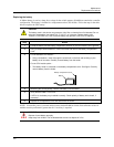
Replace battery with Tadiran TL5101/S
only. Use of another battery may
present a risk of fire or explosion.
See user’s guide for instructions.
Backplane
Battery
Compartment
Power
Supply
Fuse
Power
Supply
CPU Module
I/O Modules
Figure 35 Controller components and location