


Mounting and Wiring
Wiring Communication Links
Release F UMC800 Controller Installation and User Guide 39
4/01
Installing ferrite clamp for CE compliance
This procedure ensures that unwanted radio frequency noise is filtered. It is required for CE compliance.
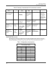
Parts needed
Part # Quantity Description
047260 1 Ferrite cable clamps
089037 2 Nylon cable ties
Installing ferrite clamp
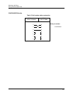
Step Action
1
Disconnect all power to the instrument.
2
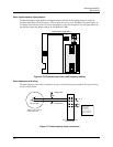
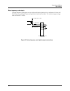
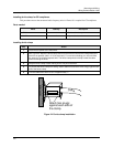
See Figure 24. Attach the ferrite clamp around all the wires as close to the Configuration port
terminals as possible (within ½” of the terminals). For maximum shielding you must minimize
the amount of unshielded exposed wire. The ferrite clamp should overlap or abut the cable
shield enclosing the wires.
3
Snap the ferrite clamp closed, making sure to not pinch the wires.
4
To prevent the ferrite clamp from sliding, attach cable ties around the wires snugly against each
end of the ferrite clamp.
5
Trim the cable tie but leave a “tail” of approximately 1”.
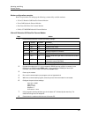
Attach ties snugly
against each side of
the clamp.
C
a
b
l
e
Terminals
Figure 24 Ferrite clamp installation