


Maintenance
Controller Calibration
68 UMC800 Controller Installation and User Guide Release F
4/01
12
11
10
9
8
7
6
5
4
3
2
1
1
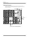
Channel 4
Channel 3
Channel 2
Channel 1
+
-
RTD
+
-
RTD
+
-
RTD
+
-
RTD
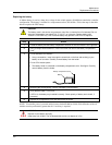
+
-
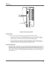
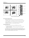
Thermocouple Input
T/C, mV, V
Ground Terminal
+
-
RTD
RTD Input (3 wires)
Ground Terminal
+
-
Current Input mA
* A 250 ohm resistor is required for
the input range.
*
Ground Terminal
4 to 20
mA
Source
+
-
mV, V Inputs
Ground Terminal
mV or V
Source
Figure 33 AI module terminal block
Other AI module calibration selections
Additional calibration selections allow you to perform other AI module calibration procedures:
• CALIBRATE CJ TEMP – for calibrating the two Cold Junction (CJ) references on the AI module
• COPY CALIBRATION – for copying calibration values from one AI module channel to another
• RESTORE AI FACTORY CAL – to restore AI module channels to their factory calibration
• RESTORE CJ FACTORY CAL – to restore CJ reference to their factory
AO module calibration values
Two calibration selections are accessible under the CALIBRATE AO menu selection
1. CALIBRATE AO CHANNEL – to calibrate the zero offset and span values of the AO module
channels to user-defined values.
2. RESTORE AO FACTORY CAL – to restore factory calibrated to an AO module channel.
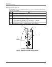
The AO module contains a wire jumper (labeled ST1) on the PWA. Cutting this jumper will prevent any
changes to initial calibration values of the module and prevent any further field calibration. See Figure 34
for the location of the jumper. More details on module calibration are given in the UMC800 Operator
Interface User Guide and the UMC800 User Utility User’s Guide.