


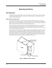
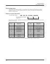

Mounting and Wiring
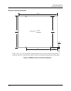
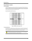
Plug-in Module Locations
20 UMC800 Controller Installation and User Guide Release F
4/01
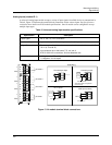
I/O module limits
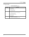
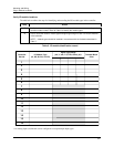
The controller backplane accommodates I/O module types, subject to the limitations as shown in Table 7.
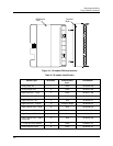
Slot Locations identify the allowable locations in the controller for each I/O module type. Maximum
Allowed describes the maximum I/O configuration for each I/O type in a controller.
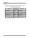
Table 7 I/O module installation limitations
I/O Module Type Slot Locations
(See Figure 9)
Maximum Allowed
Universal Analog Input (ID: 1) 1 through 16 16 modules (64 points)
Analog Output (ID: 2) 1 through 10 4 modules (16 points)
Digital Input (ID: 3,4,5) 1 through 16 16 modules (96 points)*
Digital Input 16 point (ID: B) 14 through 16 3 modules (48 points)*
Digital Output (ID: 6,7,8) 1 through 8 8 modules (48 points)*
Digital Output (ID: A) 9 through 16 2 modules (12 points)*
± 15 Vdc pH Power Module (ID: C) 5, 6 2 modules (8 points)
Pulse/Frequency Input (ID: D) 1 through 16 16 modules (64 points)
NOTE: Total combined I/O of all types is limited by the 16 available controller I/O slots.
* Total of 96 DI/DOs allowed for all types combined.