


Mounting and Wiring
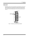
Signal Wiring
Release F UMC800 Controller Installation and User Guide 31
4/01
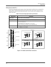
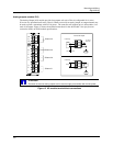
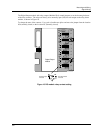
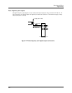
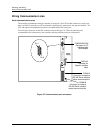
The Digital Output module with relay outputs (Module ID 6) contain jumpers to set the de-energized state
of the relay contacts. The relays are factory set to normally open (NO) for each output on the relay alarm
module, as shown in Figure 18.
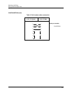
To change the state of the contacts: Use a pair of needle-nose pliers and move the jumper from the location
NO (normally closed) to the location NC (normally closed).
11
12
10
NO NC
!
8
9
7
5
6
4
2
3
1
Digital Output
Module
S1
NC1
NO1
S2
NC2
NO2
S3
NC3
NO3
S4
NC4
NO4
S5
NC5
NO5
S6
NC6
NO6
NC
NO
Normally Open
Contacts
Normally Closed
Contacts
Figure 18 DO module relay contact setting