


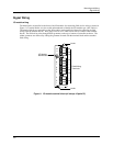
Mounting and Wiring
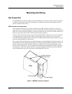
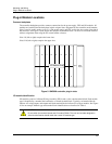
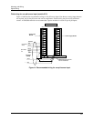
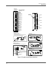
Plug-in Module Locations
22 UMC800 Controller Installation and User Guide Release F
4/01
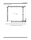
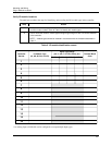
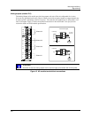
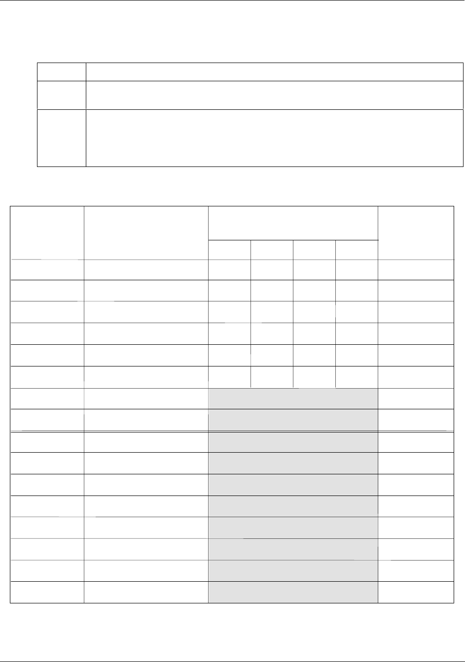
Verify I/O module locations
The table below outlines the steps for identifying and recording the I/O module types in the controller.
Step Action
1
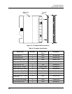
Verify that the module types installed in the controller card slots are correct according to the
controller model number. Refer to Table 6 to identify the module types.
2
Use to record the location, module type and signal type/range for each I/O module installed
in the controller.
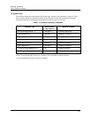
NOTE Module types should be installed in accordance with the limitations described in
Table 7.
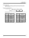
Table 8 I/O module identification record
Controller
Slot No.
I/O Module Type
(AI, AO, DI, DO, or PI/FI)
Terminal Block
Color
Signal Type/Range
(mV, V, mA, T/C, RTD, Ohms, pH)*
Al Ch 1 Al Ch 2 Al Ch 3 Al Ch 4
1
2
3
4
5
6
7
8
9
10
11
12
13
14
15
16
* An Analog Input (AI) Module can be configured to accept multiple input types.