


Maintenance
Controller Calibration
66 UMC800 Controller Installation and User Guide Release F
4/01
Factory calibration
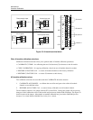
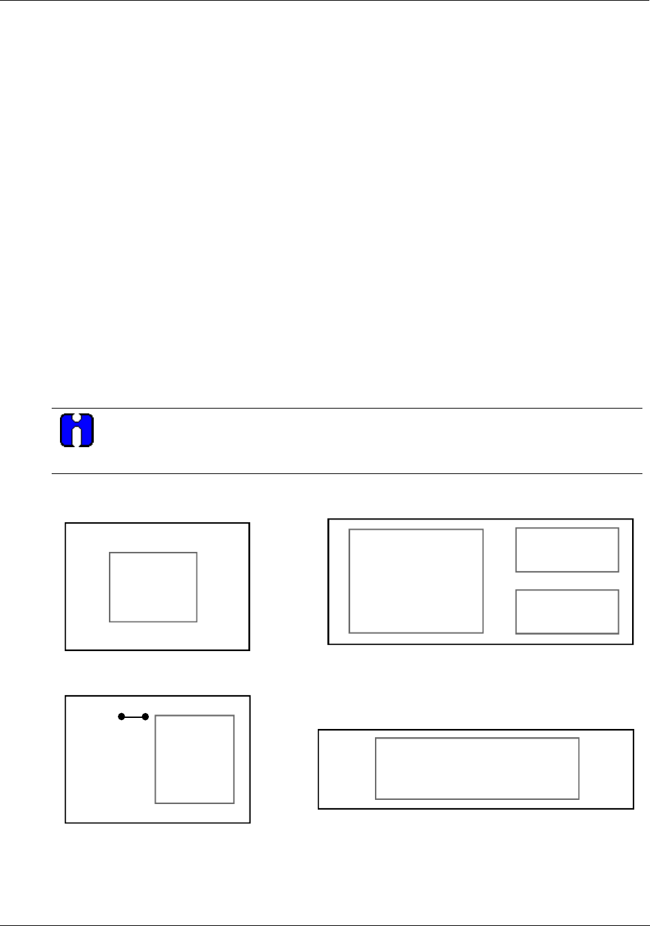
Factory calibration of controller components is performed before shipment to 0.1% accuracy. Calibration
values are contained in a number of the controller components, namely: the CPU, Backplane, and AI and
AO modules.
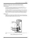
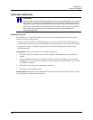
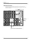
Figure 32 shows the various components in which calibration data is stored.
• Calibration functions and parameters for the user interface are stored in memory on the CPU.
• Each AI module contains two (2) cold junction compensation (CJC) references that are factory
calibrated. Factory calibration data for the CJC references is stored in a non-volatile memory on the AI
module.
• Field calibration values for the AI modules (both zero offset and span calibration and CJC reference
values) are stored on the CPU.
• Factory calibration values (zero offset and span corrections) for AO modules are stored in non-volatile
memory on the AO module and can be changed only if the write protect jumper is not cut. See Write
Protect Jumper ST1.
• The gains and offsets of the preamp are factory calibrated and the calibration data is stored in a non-
volatile memory on the backplane. No field calibration of these values is possible.
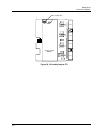
Write Protect Jumper ST1
ATTENTION
A jumper (ST1) on the AO module PWA can be cut to prevent changes to calibration values.
This will write protect the AO and prevent further calibration of these values.
AO Module
AO01
AO02
AO03
AO04
Factory
& Field
Calibration
Values
ST1
AI Module
AI01
AI02
AI03
AI04
CJC Factory
Calibration
Values
CJC
CJC
Factory Calibrated
Preamp Gains and Offsets
(for AI and CJC)
Backplane
CPU
Calibration
Function
Calibration
User Interface
Field
Calibration
Values
(AI and CJC)
in Battery-backed RAM
Figure 32 Controller components that contain calibration values