


Diagnostics and Troubleshooting
Fault Detection and Troubleclearing
Release F UMC800 Controller Installation and User Guide 87
4/01
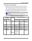
Fault detection and troubleclearing
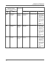
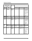
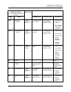
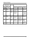
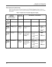
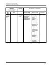
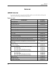
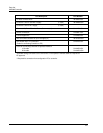
Table 21 describes the status messages that appear on the I/O Module Diagnostics displays in the user
utility and operator interface, as well as the status indications of the POWER LED located on the controller
CPU module.
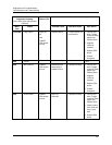
Table 21 Details of the I/O module diagnostics display
I/O Module
Diagnostics
(In The User Utility and
Operator Interface)
Controller
LED on CPU
Fault Detection / Troubleclearing
Menu
Item
Status Possible Cause Controller Action User Action
MODULE
1 through
MODULE
16
GOOD
−− − −
MODULE
1 through
MODULE
16
HI CJ
TEMPERATURE
POWER
LED flashes
10 times
High cold junction
temperature on AI
module.
Executes normally.
1. Improve
ventilation to
rack.
2. Replace AI
module
MODULE
1 through
MODULE
16
WRONG
MODULE
POWER
LED flashes
11 times
The module does
not agree with the
module required
for the control
strategy.
These function
block types do the
following:
AI – sets its output
to failsafe
DI – sets its output
to OFF
1. Replace
module.
2. Check
configuration.
MODULE
1 through
MODULE
16
NO MODULE POWER
LED flashes
11 times.
No module found
in the slot that
requires a module
for the control
strategy.
These function
block types do the
following:
AI – sets its output
to failsafe
DI – sets its output
to OFF
1. Install the
correct type of
module.
2. Check
configuration.