


Maintenance
Replacement Procedures
76 UMC800 Controller Installation and User Guide Release F
4/01
Replacing the power supply module
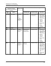
Step Action
1
Remove power from controller.
2
Disconnect power wiring from power supply terminals.
3
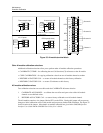
Remove front cover by loosening the two screws at the top of the enclosure.
4
Remove five screws on the front of power supply securing the CPU module and power supply.
5
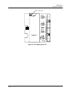
Unplug CPU module from controller slot by pulling it straight out from its slot.
6
Unplug power supply module from controller by pulling it straight out from its slot.
7
Plug in the replacement power supply into the enclosure slot and carefully insert CPU module
into its slot.
8
Secure power supply and CPU with five screws.
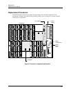
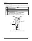
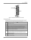
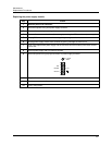
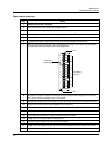
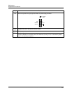
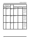
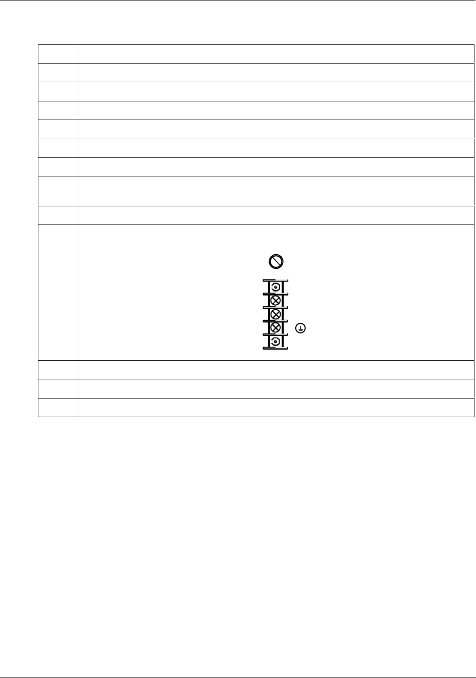
9
Reconnect power wiring to proper terminals on power supply as shown.
Hot
Neutral
Ground
F 3,15 AT
250V
L1
L2 / N
10
Replace front cover and secure with two screws.
11
Restore power to controller.
12
Verify configuration.