


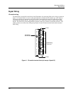

Mounting and Wiring
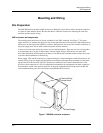
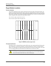
Plug-in Module Locations
Release F UMC800 Controller Installation and User Guide 19
4/01
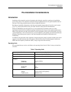
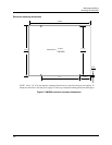
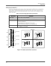
OUT 4
+
_
OUT 3
+
_
OUT 2
+
_
OUT 1
+
_
0-20
mA
!
I/O Module
PWA
Terminal
Block
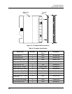
Figure 10 I/O module PWA and terminal
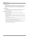
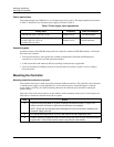
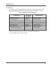
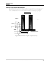
Table 6 I/O module identification
Module Type ID Number
Terminal Block
Color
Part Number
Analog Input (AI) 1 Black 46190305-503
Analog Output (AO) 2 Black 46190314-503
Digital Input (DI) - Logic 3 Black 46190311-503
Digital Input (DI) - DC 4 Black 46190347-501
Digital Input (DI) - AC 5 Red 46190350-501
Digital Input (DI) - 16 point B Orange or Beige 46190353-501
Digital Outputs (DO) - Relay 6 Red 46190308-503
Digital Outputs (DO) - DC 7 Black 46190341-501
Digital Outputs (DO) - AC 8 Red 46190344-501
Digital Outputs (DO) - Higher
Current AC
A Red 46190344-502
± 15 Vdc pH Power Module C Black 51450921-501
Pulse/Frequency Input D Black 46190360-501