


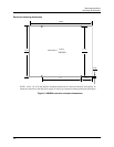
Mounting and Wiring
Signal Wiring
Release F UMC800 Controller Installation and User Guide 25
4/01
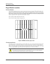
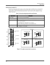
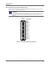
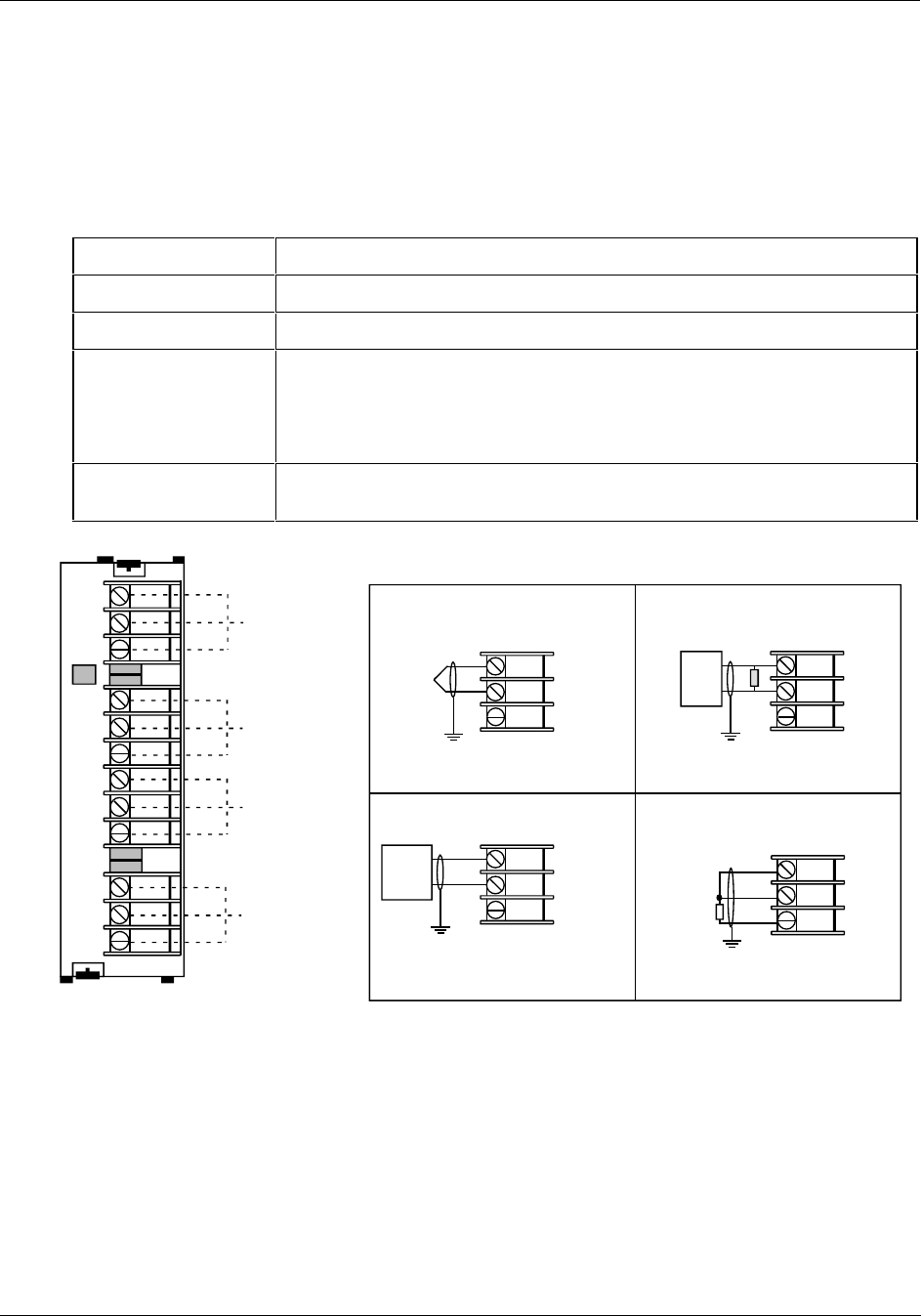
Analog inputs (module ID 1)
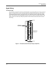
A universal Analog Input module accepts a variety of input signals from field devices as summarized in
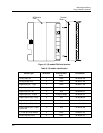
Table 9. Figure 13 illustrates the terminal block connections for the various inputs. See Specifications
section for more details on all I/O module specifications. One AI module can be configured to accept
multiple input types.
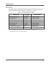
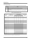
Table 9 Universal analog input module specifications
Specification Description
Input Types mV, V, mA, T/C, RTD, and Ohms
Number of Inputs 4 per module, up to 16 modules per controller (64 inputs)
Signal Source
Thermocouple with cold junction compensation, for operation between 32 °F to
176 °F (0 °C to 80 °C)
Line resistance up to 1000 ohms, T/C, mV, mA, V
RTD Pt 100 3-wire connections, 40 ohms balanced max.
Input Impedance
10 Megohms for T/C, mV inputs,
> 1 Megohms for volt inputs
12
11
10
9
8
7
6
5
4
3
2
1
1
Channel 4
Channel 3
Channel 2
Channel 1
+
-
RTD
+
-
RTD
+
-
RTD
+
-
RTD
+
-
Thermocouple Input
T/C, mV, V
Ground Terminal
+
-
Ground Terminal
RTD
RTD Input (3 wires)
+
-
Current Input mA
* A 250 ohm resistor is required for
the input range.
*
Ground Terminal
4 to 20
mA
Source
+
-
mV, V Inputs
Ground Terminal
mV or V
Source
Field Wiring
Figure 13 AI module terminal block connections