


Equipment Identification
Controller Components
Release F UMC800 Controller Installation and User Guide 5
4/01
Equipment Identification
Controller Components
Enclosure
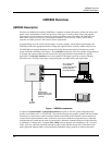
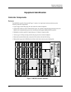
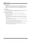
The UMC800 controller illustrated in Figure 2 consists of a single metal enclosure that houses the
following controller components:
• Power supply module that plugs into the controller common backplane.
• CPU module with two serial communications ports. An optional communications board provides two
RS485 serial communication ports (slave and master) that support Modbus® RTU protocol.
• Backplane assembly capable of supporting up to 16 input or output modules.
• Various types of I/O processing modules that plug into the common backplane.
• Removable terminal blocks that connect the I/O modules with the field wiring.
• Battery back-up power for RAM and real time clock in the event of power interruption.
12
11
10
9
8
7
6
5
4
3
2
1
12
11
10
9
8
7
6
5
4
3
2
1
12
11
10
9
8
7
6
5
4
3
2
1
_
100 - 240 V ~
50 / 60 Hz
100 VA MAX.
F 3,15 A T
250V
L1
L2 / N
12
11
10
9
8
7
6
5
4
3
2
1
12
11
10
9
8
7
6
5
4
3
2
1
12
11
10
9
8
7
6
5
4
3
2
1
12
11
10
9
8
7
6
5
4
3
2
1
12
11
10
9
8
7
6
5
4
3
2
1
12
11
10
9
8
7
6
5
4
3
2
1
12
11
10
9
8
7
6
5
4
3
2
1
12
11
10
9
8
7
6
5
4
3
2
1
12
11
10
9
8
7
6
5
4
3
2
1
POWER
LoBAT
FORCE
RUN
DISPLAY
BAT
CONFIGURATION
OFFLINE
RUN
PROGRAM
COMM B COMM A
Replace battery with Tadiran TL5101/S
only. Use of another battery may
present a risk of fire or explosion.
See user’s guide for instructions.
Figure 2 UMC800 controller hardware