


Mounting and Wiring
Plug-in Module Locations
18 UMC800 Controller Installation and User Guide Release F
4/01
Plug-in Module Locations
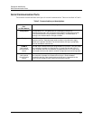
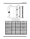
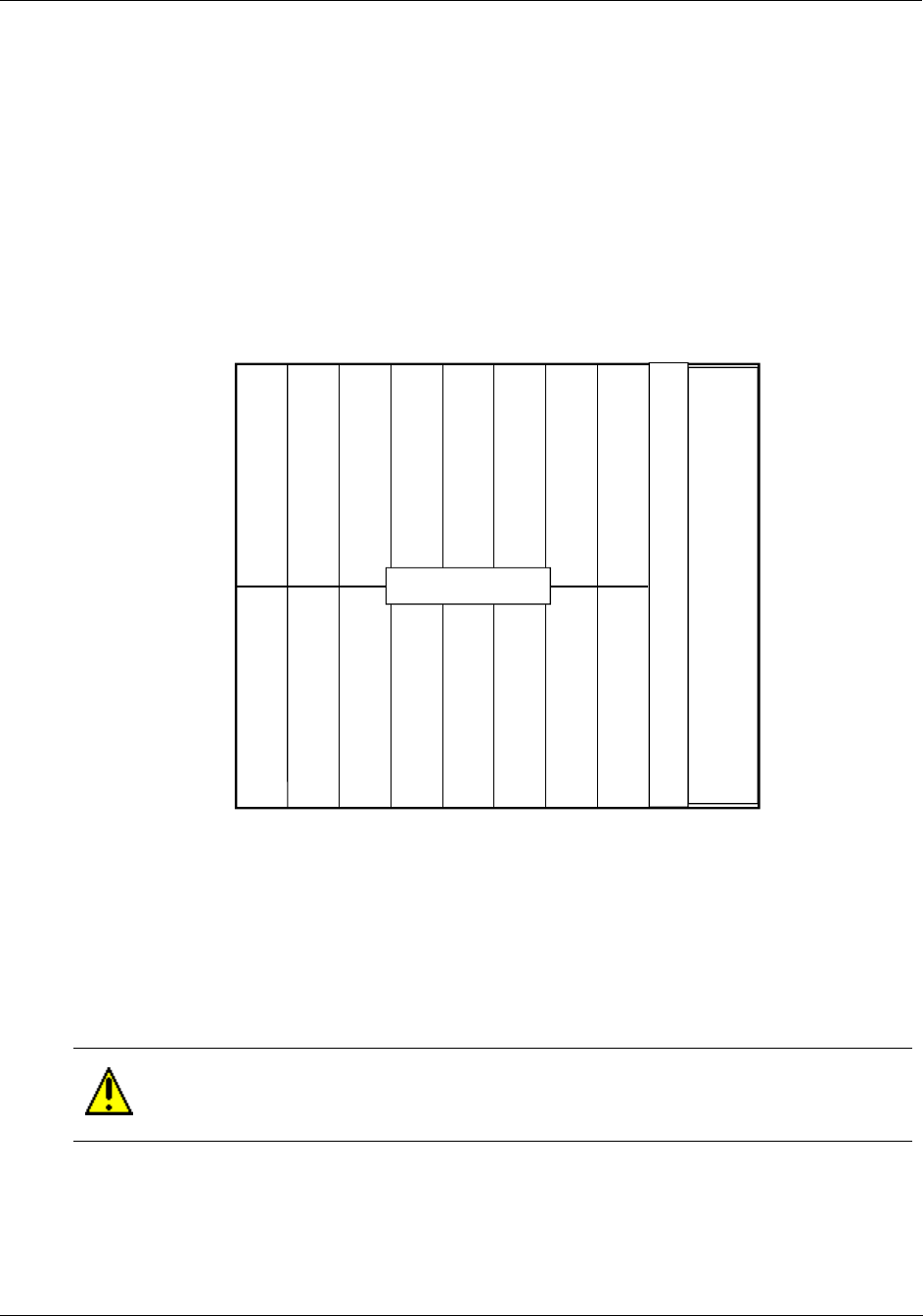
Common backplane
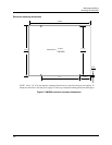
The controller backplane provides common connections for the power supply, CPU and I/O modules. All
modules are installed into the backplane in their assigned slots designated by the controller model number.
[See Controller model number (page 21).] The power supply and CPU occupy the slots on the right side of
the enclosure. See Figure 9. Slots for the I/O modules are numbered from 1 to 16 to be consistent with I/O
address assignment when using the PC control builder software.
Slots 1-8 (left to right) comprise the lower slots.
Slots 9-16 (left to right) comprise the upper slots.
CPU
Power
Supply
I/O Module Slots
1 2 3 4 5 6 7 8
9 10 11 12 13 14 15 16
Figure 9 UMC800 controller plug-in slots
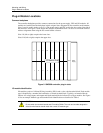
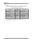
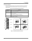
I/O module identification
I/O modules consist of a Printed Wiring Assembly (PWA) and a color-coded terminal block. Each module
type is identified by a number label attached to a colored terminal block. Typically, red terminal blocks
indicate AC voltage inputs and outputs and black terminal blocks indicate low voltage modules. See Figure
10 for an example. Module type and terminal block identification are described in Table 6.
CAUTION
Do not switch the terminal boards and I/O module PWAs. The color and number designation
of the terminal boards should match the correct I/O module type.