


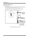

Mounting and Wiring
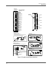
Signal Wiring
Release F UMC800 Controller Installation and User Guide 33
4/01
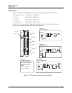
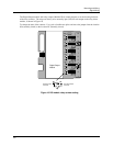
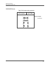
Pulse input/frequency input jumpers
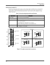
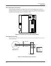
The Pulse/Frequency Input Module with Digital Outputs (Module ID D) contain jumpers to set the de-
energized Input Filter Cutoff Frequency. All four inputs are factory set to 500 KHz as shown in Figure 23.
To change, use needle nose pliers and move the jumper(s) to the desired position. See the figure below for
the default positions and jumper settings for 100 KHz and 5 KHz.
4
6
1
9
0
3
6
0
-
5
0
1
OFF
ON
1
2
1
1
2
2
100KHz
5KHz
500KHz
JX1 -
JX2 -
JA1
JA2
JB1
JB2
JC1
JC2
JD2
JD1
Pulse/Frequency Input Board
Figure 20 PI/FI module input filter cutoff frequency setting
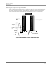
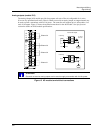
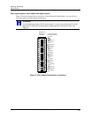
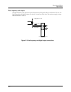
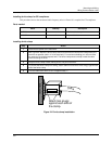
Pulse/frequency card wiring
The pulse frequency card input is designed to accept a contact closure type transmitter. The typical wiring
circuit is shown below.
V Supply (DC)
Pulse Transmitter
V Return (DC)
Pulse / Frequency Input Card
Input Connections
R
L
+
-
+
-
R
T=
1k
MOSFET, Open Collector, or
Contact Closure drive.
+
-
Note: All pulse
frequency inputs
share a return
connection that is
common to all pulse /
frequency inputs on a
card.
Figure 21 Pulse/frequency input connections