


Mounting and Wiring
Site Preparation
Release F UMC800 Controller Installation and User Guide 15
4/01
Mounting and Wiring
Site Preparation
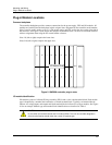
The UMC800 must be mounted within an enclosure. Hardware is provided to surface mount the controller
to a panel or other suitable surface. Be sure that there is sufficient clearance for mounting the controller
enclosure and the external wiring.
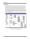
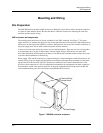
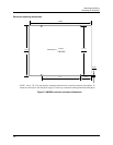
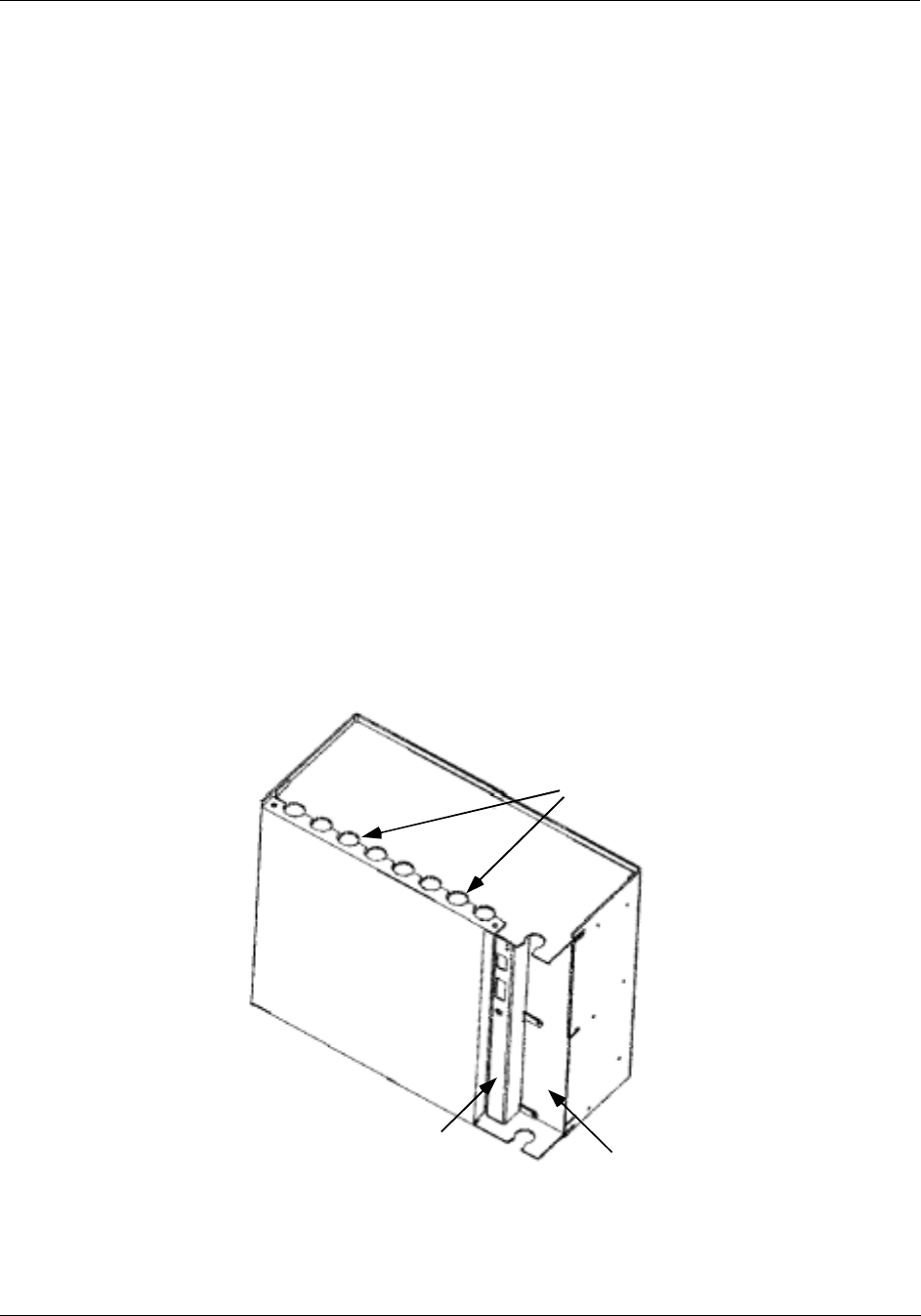
UMC enclosure and components
The controller enclosure houses all circuit assemblies of the UMC controller. See Figure 7. The power
supply and CPU are modules that plug into slots on the right hand side of the enclosure. Both modules have
metal covers on the front where indicators, switches and connectors are located. All external connections to
the power supply and CPU are made on the front panels of these modules.
A front cover can be removed by two screws to access the I/O modules. There are two rows of card guides
to accommodate up to 16 plug-in I/O modules. External signal wiring to field devices are made with
removable terminal blocks that attach to the front of each I/O module. Optional terminal strips can be used
to provide shield termination of field wiring.
Power supply, CPU and I/O modules are connected through a common backplane within the enclosure. All
external wiring for power supply and I/O modules are brought out through rubber grommets located at the
top and bottom of the enclosure. The CPU features two connections for external communications. One
provides a cable connection to a PC for configuration and database file management; the other connection
accommodates a cable to the operator interface. An optional communication board provides two RS 485
serial communications ports (slave and master) using Modbus RTU protocol.
CPU Module
Power Supply
Front
Cover
External Wiring
Access Holes
Figure 7 UMC800 controller enclosure