


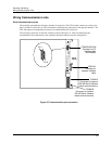
Mounting and Wiring
Signal Wiring
Release F UMC800 Controller Installation and User Guide 29
4/01
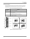
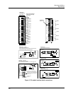
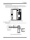
12
11
10
9
8
7
6
5
4
3
2
1
DI 6
DI 4
DI 3
DI 1
DI 5
DI 2
Module ID
#3, 4, or 5
32
30
28
26
24
22
20
18
16
14
12
10
8
6
4
2
Module B
Identifiable by
32 screws
Each odd-numbered
terminal is internally
grounded.
DI 1
DI 2
DI 7
DI 3
DI 4
DI 5
DI 6
DI 8
DI 9
DI 10
DI 11
DI 12
DI 13
DI 14
DI 15
DI 16
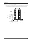
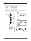
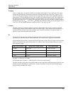
+
Gnd
R
+ VCC
+
-
+
24V
-
Field Wiring
Module ID #4
DC Input (24 Vdc)
Gnd
R
+ VCC
Field Wiring
Module ID #3
Logic Input (Contact Closure)
R
+ VCC
Module ID B (16 DI)
Logic Input (Contact Closure)
Field Wiring
Gnd
Dry SW
Logic
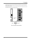
For 2 wires per DI, must use 22-gage wire to fit 32
wires through rubber grommet on case.
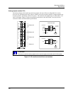
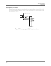
L1
L2
R
+ VCC
Field Wiring
Module ID #5
AC Input (120/240 Vdc)
Dry SW
R
+ VCC
Module ID B (16 DI)
Logic Input (Contact Closure)
Field Wiring
Gnd
Logic
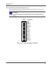
• One wire per DI. Each wire goes to
Marshalling field connector (user provided).
• One common wire from Marshalling field
connector to any ground connector on the
16 pt. DI terminal.
For 1 common wire for all DIs, use 16-22 gage wire.
Marshalling field
connector
Dry SW
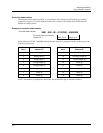
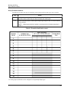
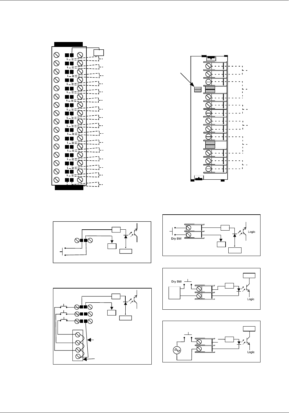
Figure 16 DI module terminal block connections