


Mounting and Wiring
Wiring Communication Links
36 UMC800 Controller Installation and User Guide Release F
4/01
Wiring Communication Links
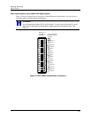
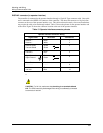
Serial communications ports
The controller communicates through a number of serial ports. The CPU module contains two serial ports.
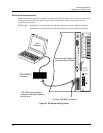
One is an RS 232 connection to a PC and another is dedicated for connection to the operator interface. The
CPU with optional communications features two additional RS 485 serial ports.
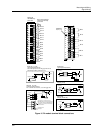
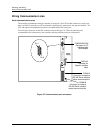
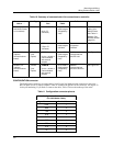
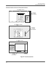
The serial port connectors on the CPU module are shown in Figure 23. Table 10 summarizes the
communication link connections to the controller and other reference data for wiring details.
Power
Supply
DISPLAY
Connector for
Operator Interface
cable
CONFIGURATION
Connector for PC
Interface cable
(Null Modem)
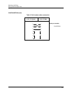
Pin 1
Pin 9
POWER
LoBAT
FORCE
RUN
DISPLAY
BAT
CONFIGURATION
OFFLINE
RUN
PROGRAM
COMM B COMM A
Replace battery with Tadiran TL5101/S
on ly. Us e o f an othe r ba tter y ma y
pre se nt a risk of fire or explosion .
See users guide for instructions.
CPU
COMM A
Connector for optional
RS 485 Serial Interface
slave communications.
COMM B
Connector for optional
RS 485 Serial Interface
master communications
Figure 23 Communication port connectors