


Mounting and Wiring
Power Supply Wiring
Release F UMC800 Controller Installation and User Guide 51
4/01
Power Supply Wiring
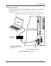
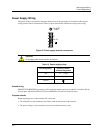
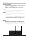
The power wiring is connected to the power terminals of the power supply in accordance with accepted
wiring practices and is summarized in Table 14 shows the terminal connections for the power wiring.
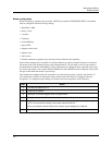
F 3,15 AT
250V
L1
L2 / N
Figure 28 Power supply terminal connections
CAUTION
Do not apply power to the controller at this time.
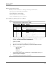
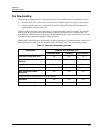
Table 14 Power supply wiring
Wire Designation Connect to Power
Terminal Designated
Hot L1 (+ DC)
Neutral L2 / N (– DC)
Ground
Ground wiring
PROTECTIVE BONDING (grounding) of this controller and the enclosure in which it is installed shall be
in accordance with National Electrical Code (ANSI/NFPA 70) and local electrical codes.
Prepower checks
Before applying power to the controller file, verify that:
• The controller has been mounted in accordance with the instructions in this manual.
• The power wiring is correct and meets all local and national electrical codes.