


Operation
RS 485 Port Configuration (Communication Board Option)
Release F UMC800 Controller Installation and User Guide 61
4/01
RS 485 Port Configuration (Communication Board Option)
COMM A and B ports
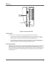
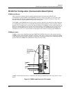
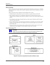
UMC controllers equipped with the optional communications board feature two RS 485 serial
communications ports (COMM A and COMM B) on the CPU module.
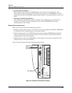
See Figure 31 for location of the
port connectors. See Wiring Communications links, Page(36) for more details on the port wiring. The
controller firmware supports Modbus RTU protocol for the ports.
The COMM A and COMM B ports must be set up so that the controller can communicate when connected
to a communication link.
Set up is accomplished through the operator interface or the user utility software
program.
The Communications screen in the operator interface for COMM A is used to enable the port, set
the device (station) address of the controller and set the baud rate. The COMM B screen is used to set the
baud rate.
See UMC800 Operator Interface User Guide for details on communications port setup. See
UMC800 User Utility User’s Guide and the on-line help for more details on setting up the COMM ports.
COMM port status
COMM A status can be checked through the COMMUNICATIONS menu item on the operator interface.
COMM B status can be monitored with the User Utility. Slave device statuses can be viewed after loading
a configuration into User Utility via upload or floppy disk. Slave devices must first be enabled through the
operator interface COMMUNICATIONS menu item or the User Utility.
_
100 - 24 0 V ~
50 / 6 0 Hz
100 VA MAX.
F 3,15 A T
250V
L1
L2 / N
POWER
LoBAT
FORCE
RUN
DISPLAY
BAT
COMM B COMM A
Re
pl
ace
batter
y with
Tadira
n TL5101/S
on
ly
. Use of ano
th
er
ba
t
te
ry may
prese
nt
a risk of fire or ex
plosi
on.
See use
rs
g
ui
de for i
nstructions
.
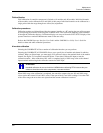
COMM A
Port
CPU Module
with Optional
Communications
Board
COMM B
Port
COMM A and B shown with 2-wire connections. See Wiring Communications links, Page(36) for 4-wire
details.
Figure 31 COMM A and B ports on CPU module