


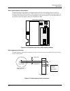
Mounting and Wiring
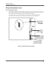
Wiring Communication Links
Release F UMC800 Controller Installation and User Guide 37
4/01
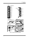
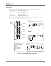
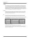
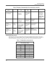
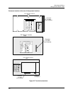
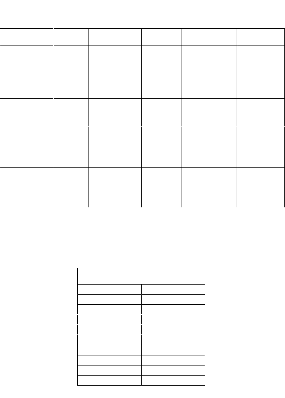
Table 10 Summary of communication link connections to controller
Communication
Link to . . .
Link Type
From Controller
Port
Connect
Cable
To Port Reference Data
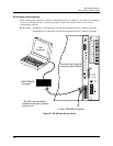
PC or laptop (via
Null Modem cable
or via modem)
RS 232
CONFIGURATION
(9-pin “D”
connector)
Up to 50 ft
cable lengths
(Supplied by
user)
Serial port of PC. Null Modem
cable, 9-pin
Male/Female
See Table 11.
Modem: See
Remote Access
(page 44)
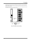
Operator interface RS 422
DISPLAY
(15-pin “D”
connector)
10 ft or 50 ft
cable lengths
available.
Terminal connector
of operator
interface.
See Table 12.
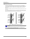
Modbus Link
(optional
communications
board)
RS 485
(Half
Duplex)
COMM A
(4-wire + shield or
2-wire shielded
with external
jumpers
Up to 2000 ft
cable lengths
(Supplied by
user)
Modbus
communications
and PC host.
See Figure 26.
Modbus Link
(optional
communications
board)
RS 485
(Half
Duplex)
COMM B
(4-wire + shield or
2-wire shielded
with external
jumpers
Up to 2000 ft
cable lengths
(Supplied by
user)
Modbus
communications
and slave devices.-
See Figure 26.
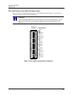
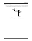
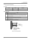
CONFIGURATION connector
The Configuration connector accommodates a 9-pin D-type Null Modem cable connection to the serial
RS-232 input of a PC or laptop computer. Table 11 describes the pinouts for the connector. See Figure 23
for the pin numbering. If you need to construct the cable, Table 12 shows the make up of the cable.
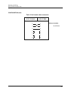
Table 11 Configuration connector pinouts
Configuration Connector Pinouts
(For Null Modem Cable)
Signal Name Terminal No.
DCD 1
RXD 2
TXD 3
DTR 4
GND 5
DSR 6
RTS 7
CTS 8
RI 9