


8051
Architectural Specification and Functional Description
time
is
IllS
and the access times required from stable
address and from read (RD) or write (WR) command are
approximately 600ns and 250ns respectively.
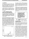
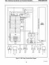
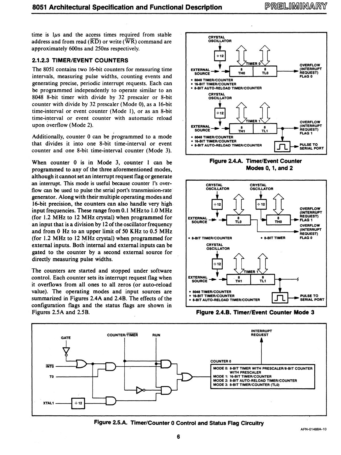
2.1.2.3 TIMER/EVENT COUNTERS
The
8051
contains two 16-bit counters for measuring time
intervals, measuring pulse widths, counting events and
generating precise, periodic interrupt requests. Each can
be programmed independently to operate similar to an
8048
8-bit timer with divide
by
32
prescaler or 8-bit
counter with divide by
32
prescaler (Mode 0), as a 16-bit
time-interval or event counter (Mode I), or
as
an 8-bit
time-interval or event counter with automatic reload
upon overflow (Mode
2).
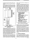
Additionally, counter 0 can be programmed to a mode
that divides it into one 8-bit time-interval
or
event
counter and one 8-bit time-interval counter (Mode
3).
When counter 0
is
in Mode
3,
counter I can be
programmed to any
of
the three aforementioned modes,
although it cannot set an interrupt request flag
or
generate
an interrupt. This mode
is
useful
because counter
I's
over-
flow
can be
used
to pulse the serial port's transmission-rate
generator. Along with their multiple operating modes and
16-bit precision, the counters can also handle very high
input frequencies. These range from
0.1
MHzto
1.0
MHz
(for
1.2
MHz to
12
MHz
crystal) when programmed for
an input that
is
a division by
12
of the oscillator frequency
and from
0 Hz to an upper limit
of
50
KHz to 0.5 MHz
(for
1.2
MHz to
12
MHz crystal) when programmed for
external inputs.
Both· internal and external inputs can be
gated to the counter by a second external source for
directly measuring pulse widths.
The counters are started and stopped under software
control. Each counter sets its interrupt request flag when
it overflows from all ones to
aU
zeros (or auto-reload
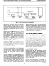
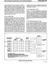
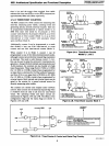
value). The operating modes and input sources are
summarized
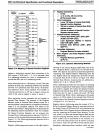
in Figures 2.4A and 2.4B. The effects
of
the
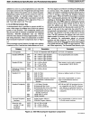
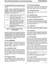
configuration flags and the status flags are shown in
Figures 2.5A and 2.5B.
GATE
COUNTER/TIMER RUN
INTO
--~=-~l:'~>-"t"--r-\--J====j~:J
TO------~
XTAl1
CRYSTAL
OSCILLATOR
$
EXTERNAL-.
SOURCE
•
8048 TIMER/COUNTER
• 16-BIT TIMER/COUNTER
• 8-BIT AUTO-RELOAD
TIMER/COUNTER
CRYSTAL
OVERFLOW
~_--I~
(INTERRUPT
REQUEST)
FLAG 0
OVERFLOW
°ii~O,.R
__
~~~~~
__
~
EXTSOEURRNCALE
-.
1---4t----I~
(INTERRUPT
REQUEST)
•
8048 TIMER/COUNTER
• 16-BIT TIMER/COUNTER
• 8-BIT AUTO-RELOAD TIMER/COUNTER
FLAG 1
PULSE TO
SERIAL PORT
Figure 2.4.A. Timer/Event Counter
Modes
0,
1,
and 2
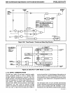
CRYSTAL
OSCilLATOR
$
EXTERNAL
___
SOURCE
CRYSTAL
OSCILLATOR
OVERFLOW
(INTERRUPT
REQUEST)
FLAG
1
OVERFLOW
L--
____
--I~ (INTERRUPT
REQUEST)
FLAG 0
• 8-BIT TIMER/COUNTER
CRYSTAL
OSCilLATOR
$
EX;5~:~~'"
• 8048 TIMER/COUNTER
• 16-BIT TIMER/COUNTER
• 8-BIT AUTO-RELOAD TIMER/COUNTER
• 8-BIT
TIMER
PULSE TO
SERIAL PORT
Figure 2.4.8. Timer/Event Counter Mode 3
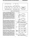
COUNTER 0
INTERRUPT
REQUEST
MODE
0:
8-BIT TIMER WITH PRESCALER/8-BIT COUNTER
WITH PRESCAlER
>----f
MODE
1:
16-BIT TIMER/COUNTER
MODE
2:
8-BIT AUTO-RELOAD TIMER/COUNTER
MODE
3:
8-BIT TIMER/COUNTER (TlO)
Figure
2.S.A.
Timer/Counter 0 Control and Status Flag Circuitry
AFN-01488A-l0
6