


8051 Architectural Specification and Functional Description
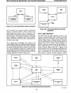
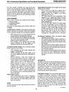
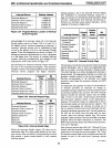
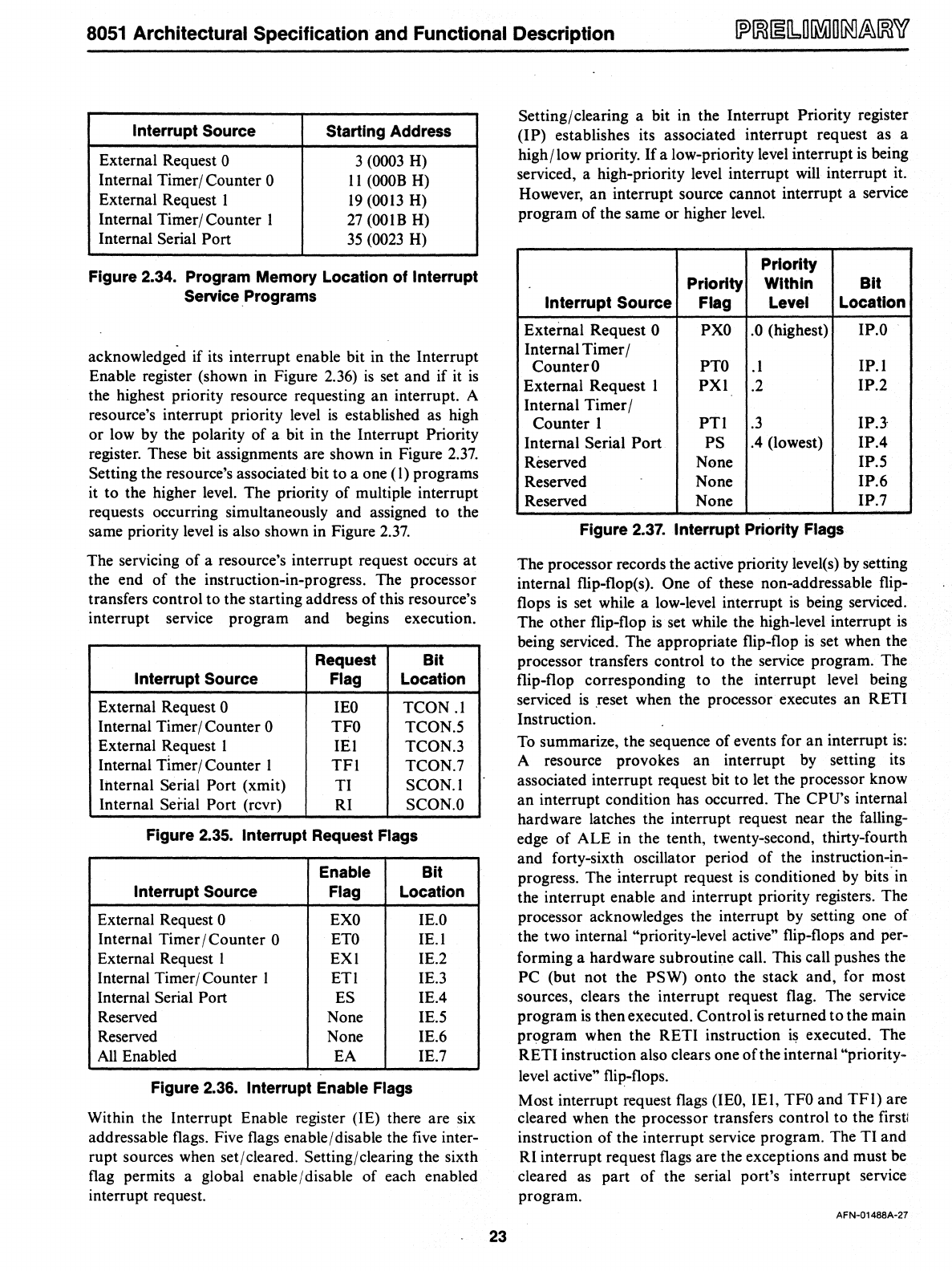
Interrupt Source
Starting Address
External Request 0
3
(0003
H)
Internal Timer/Counter 0
II
(OOOB
H)
External Request I
19
(0013
H)
Internal Timer/ Counter I
27
(OOIB
H)
Internal Serial Port
35
(0023
H)
Figure 2.34. Program Memory Location of Interrupt
Service
Programs
acknowledged if its interrupt enable bit in the Interrupt
Enable register (shown in Figure 2.36)
is
set and if it
is
the highest priority resource requesting an interrupt. A
resource's interrupt priority level
is
established as high
or low by the polarity of a bit in the Interrupt Priority
register. These bit assignments are shown in Figure
2.37.
Setting the resource's associated bit to a one (1) programs
it to the higher level. The priority of
mUltiple interrupt
requests occurring simultaneously and assigned to the
same priority
level
is
also shown in Figure
2.37.
The servicing of a resource's interrupt request occurs
at
the end of the instruction-in-progress. The processor
transfers control to the starting address of this resource's
interrupt service program and begins execution.
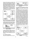
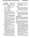
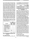
Request Bit
Interrupt Source
Flag
Location
External Request 0
lEO
TCON
.1
Internal Timer/ Counter 0
TFO
TCON.5
External Request I
lEI
TCON.3
Internal
Timer/ Counter I
TFI
TCON.7
Internal Serial
Port (xmit)
TI
SCON.I
Internal
Serial Port (rcvr)
RI
SCON.O
Figure 2.35. Interrupt Request Flags
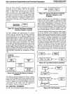
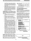
Enable
Bit
Interrupt Source Flag Location
External Request 0
EXO
lE.O
Internal Timer / Counter 0
ETO
IE.!
External Request I EXI
1E.2
Internal Timer/ Counter 1 ETI IE.3
Internal Serial
Port
ES
1E.4
Reserved None
1E.5
Reserved None
1E.6
All
Enabled
EA
1E.7
Figure 2.36. Interrupt Enable Flags
Within the Interrupt Enable register (IE) there are six
addressable flags. Five flags enable / disable the
five
inter-
rupt sources when set/cleared. Setting/clearing the sixth
flag permits a global enable
I disable of each enabled
interrupt request.
23
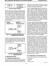
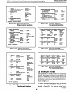
Setting/ clearing a bit in the Interrupt Priority register
(IP) establishes its associated interrupt request as a
high/low priority.
If
a low-priority level interrupt
is
being
serviced, a high-priority level interrupt will interrupt it.
However, an interrupt source cannot interrupt a service
program of the same or higher level.
Priority
Priority Within
Bit
Interrupt Source Flag Level
Location
External Request 0
PXO
.0 (highest)
IP.O
Internal Timer /
Counter
0
PTO
.1
IP.l
External Request 1
PXl
.2
IP.2
Internal Timer /
Counter I
PTI
.3
IP.J
Internal Serial
Port
PS
.4
(lowest) IP.4
Reserved
None
IP.5
Reserved None
IP.6
Reserved None
IP.7
Figure 2.37. Interrupt Priority Flags
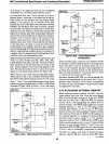
The processor records the active priority level(s)
by
setting
internal flip-flop(s).
One of these non-addressable flip-
flops
is
set while a low-level interrupt
is
being serviced.
The other flip-flop
is
set while the high-level interrupt
is
being serviced. The appropriate flip-flop
is
set when the
processor transfers control to the service program. The
flip-flop corresponding to the interrupt level being
serviced
is
reset when the processor executes an RETI
Instruction.
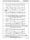
To
summarize, the sequence of events for an interrupt
is:
A resource provokes an interrupt
by
setting its
associated interrupt request bit to let the processor know
an interrupt condition has occurred. The
CPU's internal
hardware latches the interrupt request near the falling-
edge of ALE in the tenth, twenty-second, thirty-fourth
and forty-sixth oscillator period of the instruction-in-
progress. The Interrupt request
is
conditioned
by
bits in
the interrupt enable and interrupt priority registers. The
processor acknowledges the interrupt
by
setting one of
the two internal
"priority-level active" flip-flops and per-
forming a hardware subroutine call. This call pushes the
PC (but not the PSW) onto the stack and, for most
sources, clears the interrupt request flag. The service
program
is
then executed. Control
is
returned to the main
program when the RETI instruction
is
executed. The
RETI instruction also clears one of the internal
"priority-
level active" flip-flops.
Most interrupt request flags
(lEO,
lEt,
TFO
and
TFl)
are
cleared when the processor transfers control to the firstl
instruction of the interrupt service program. The TI and
RI interrupt request flags are the exceptions and must be
cleared as part of the serial port's interrupt service
program.
AFN-01488A-27