


8051
Architectural Specification and Functional Description
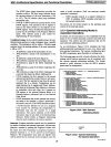
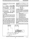
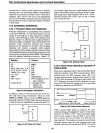
The functions
of
the bits in
TMOD
are shown in Figure
2.45. Recall from section
2.3
that the bits in
TMOD
are
not bit addressable.
Bit
Function
Flag
Location
Enable input
at
TI using INTI
Gate TMOD.7
Counter
1/
Timer 1 select
CIT
TMOD.6
C
I/T
1 Mode select MSb
Ml
TMOD.5
C
I/T
I Mode select LSb
MO
TMOD.4
Enable input to
TO
using
INTO
Gate TMOD.3
-
Counter 0/ Timer 0 select
CIT
TMOD.2
C
OfT
0 Mode select MSb
Ml
TMOD.l
C 0/ T 0 Mode select LSb
MO
TMOD.O
Figure 2.45. Functions of Bits
in
TMOD
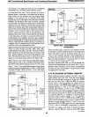
2.11.3 Operation
The counter circuitry counts up
to
all l's and then
overflows to either
O's
or
the reload value. Upon
overflow,
TFI
or
TFO
gets set. When an instruction
changes the timer's mode
or
alters its control bits, the
actual change occurs at the end
of
the instruction's
execution.
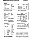
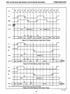
The T I and
TO
inputs are sampled near the falling-edge
of ALE in the tenth, twenty-second, thirty-fourth and
forty-sixth oscillator periods
of
the instruction-in-
progress.
They are also sampled in the twenty-second
oscillator period of
MOVX despite the absence of ALE.
Thus, an external reference's high and low times must each
be a minimum
of
twelve oscillator periods in duration.
There
is
a twelve oscillator period delay from when a
toggled input (transition from high to low)
is
sampled to
when the counter
is
incremented.
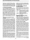
TO-----'
XTAL1
2.11.4 Reading and Reloading the Timer/
Counters
The timer/counters can be read and reloaded on the
fly.
However, the 16-bit timer/counters must be read and
loaded as two 8-bit bytes. During a read the potential
"phasing error" can be programmed around, as follows:
RTC
MOV
A,
THO
MOVB,
TLO
CJNE
A,
THO,
RTC
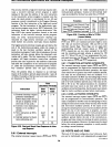
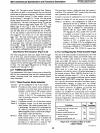
2.12 SERIAL CHANNEL
The
8051
has a serialchannel useful for serially linking
UART (universal asynchronous receiver/transmitter)
devices and for expanding
I/O.
This full-duplex serial
I/O
port can be programmed to function in one
of
four
operating modes.
Mode
0) Synchronous
I/O
expansion using
TIL
or
CMOS shift registers
Mode
1)
UART interface with to-bit frame
and variable transmission rate
Mode
2)
U
ART
interface with II-bit frame
and fixed transmission rate
Mode 3)
U
ART
interface with
II-bit
frame
and variable transmission rate
Modes 2 and 3 also provide automatic wake-up of slave
processors through interrupt driven address-frame
recognition for multiprocessor communications.
Several
schemes
of
UART interfacing are shown in Figure 2.47
and an
I/O
expansion technique
is
shown in Figure 2.48.
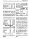
2.12.1
Serial Port Control and Data Buffer
Registers
Data for transmission and from reception reside in the
serial port buffer register
(SBUF). A write to SBUF
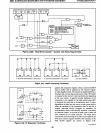
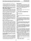
COUNTER 0
MODE
0:
8-8IT TIMER WITH PRESCALER/
8-BIT COUNTER WITH PRESCALER
MODE
1:
l8-BIT
TIMER/COUNTER
MODE
2:
8-BIT AUTO-RELOAD TIMER/COUNTER
MODE
3:
8-BIT TIMER/COUNTER
(TLO)
Figure 2.46.A. Timer/Event Counter 0 Control and Status Flag Circuitry
AFN-01488A-33
29