


8051
Architectural Specification and Functional Description
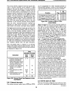
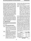
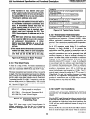
1. The hardware In each slave's serial
port
begins
by
listening
for
an addre88. Receipt
of
an addre88 frame will force an Interrupt
If
the slave's SM2
bit
Is set
to
one (1) to enable
"Interrupt
on addre88 frame only".
2. The master then transmits a frame
con-
taining the
8-blt
address
of
the slave that Is
to
receive the subsequent commands and
data. A transmitted addre88 frame has
Its
ninth data
bit
(TB8) set equal
to
one (1).
3.
When the addre88 frame Is received, each
s'ave's
serial
port
Interrupts its CPU. The
CPU then compares the addre88 sent
to
Its
own.
4.
The
8051
stave which has been addressed
then resets
Its SM2
bit
to zero (0)
to
receive
all subsequent transmissions.
All
other
8051's leave their SM2 bits at a one (1)
to
Ignore transmissions until a new address
arrives.
5.
The master device then sends
controllnfor-
matlon and data, which In
tum
Is accepted
by the previously addressed
8051
[i.e., the
one that had set
Its SM2 bit to zero (0)].
Figure 2.50. Protocol
for
Multl- Processor
Communications
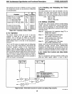
2.12.3 The Serial Frame
A frame
is
a string
of
bits. The frame transmitted
and
received in Mode 0
is
8 bits in length. The
data
bits
of
the
frame are transmitted
SBUF.O first
and
SBUF.7 last.
The frame transmitted and received in Mode
1 is ten bits
in length. The frame transmitted and received in Modes 2
and
3
is
eleven bits in length. These frames consist
of
one
start bit, eight
or
nine
data
bits and a stop bit.
Data
bits 0-
7 are loaded into SBUF.O-SBUF.7 respectively, and
data
bit 8 into RB8 (receive)
or
TB8 (transmit). With nominal
software overhead, the last
data
bit can
be
made a parity·
bit, as shown in Figure 2.51.
MOV C, P ; Parity moved to carry (byte
already in
A).
MOV TB8, C ; Put carry into Transmitter Bit 8
MOV SBUF, A; Load Transmit Register
Figure
2.51.
Generating Parity and
Transmitting Frame
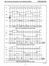
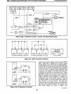
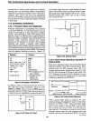
Figure 2.52 shows some typical frame formats for
different applications. The
data
bits
of
the frame are
transmitted least significant bit first
(SBUF.O) and TB8
last.
32
110BAUDTTV
I START I
DATA
.01
.1
1·21
.31
.41
.51
.61
PARITY
I
STOP
I STOP I
TYPICAL ASCII TERMINAL
I START I
DATA
.01
.1
1·21
.31 .41
.51
.61
PARITY
1 STOP I
OR
I START 1
DATA.O
1
.1
I
.21
.31
.41 .51
.6 I .7 1
PARITY
j
STOP
I
OR
I STAAT IDATA.oj
.1
1.21.31.41.51.&1.71.81
STOP I
Figur.e 2.52. Typical Frame Formats
2.12.4 Transmission Rate Generation
The proper timing for the serial
I/O
data
is
provided by a
transmission-rate generator.
On-board the
8051,
three
different methods
of
transmission rate generation are
provided. The transmission-rate achievable
is
dependent
upon the operating mode
of
the serial port.
In the
I/O
expansion mode (Mode 0) the oscillator
frequency is simply divdied by
12
to generate the
transmission rate. This produces a transmission rate
of
1M bits per second
at
12
MHz.
If
Modes
lor
3 are being
used, the transmission rate can be generated from the
oscillator frequency
or
from
an
external reference fre-
quency. In these modes, either one-twelfth the oscillator
frequency
or
the
TI
input frequency
is
divided by 256-
minus-the-value-in-TH I (counter
I must
be
configured
in auto-reload mode by software) and then divided by
32
to generate the transmission rate. When the oscillator
frequency input (rather than
TI)
is
selected, this method
produces a transmission rate
of
122
to 31,250 bits per
second (including start and stop bits)
at
12
MHz. The TI
external input
is
selected by setting the
C;Tbit
to one (1).
When Mode 2
is
used, the oscillator frequency
is
simply
divided by 64 to generate the transmission rate. This
produces
a transmission rate
of
187,500
bits per second
(including start and stop bits)
at
12
MHz.
2.12.5 UART Error Conditions
There are two
UART
error conditions
that
should be
accounted for when designing systems
that
use the serial
channel.
First, the
805I's serial channel provides no indication
that
a valid stop bit has been received. However, since a start
bit
is
detected as a high-level
to
low-level transition, the
UART
will
not
receive additional frames if a stop bit
is
not received.
Second, the RI flag
is
set and
SBUF
and RB8 are loaded
from the receiver's input shift register when the received
AFN-01488A-36