


8051 Architectural Specification and Functional Description
I
.~
~
I
TXD RXD
TXD RXD TXD
RXD
RXD TXD
TXD
RXD TXD RXD
TXD
r-----
RXD
RXD
~.
TXD
PORT PIN
CTS
8051 8051
8051 8051
8051
8051
8051
8251
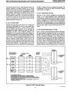
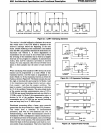
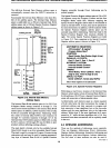
A. MULTI-80S1
INTERCONNECT
-HALF
DUPLEX B. MULTI-80S1
INTERCONNECT
-FULL
DUPLEX
C.
8051-8251 INTERFACE
Figure 2.7.
UART
Interfacing Schemes
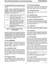
The receiver
is
double buffered to eliminate the overrun
that would occur if the
CPU
failed to respond to the
receiver's interrupt before the beginning
of
the next
frame. Double buffering
of
the transmitter is not needed
since the
8051
can generally maintain the serial link
at
its
maximum rate without it. A minor degradation in
transmission rate can occur in rare events such as when
the servicing
of
the transmitter has to wait for a lengthy
interrupt service program to complete. In asynchronous
modes, false start-bit rejection
is
provided on received
frames.
For
noise rejection a best two-out-of-three vote
is
taken on three samples near the center
of
each received
bit.
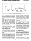
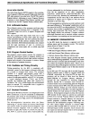
When interfacing with standard UART devices the serial
channel can be programmed to a mode (Mode
1)
that
transmits/ receives a ten-bit frame
or
programmed
to
a
mode (Mode 2
or
3)
that transmits/receives an eleven-bit
frame as shown in Figure 2
..
9.
The frame consists
of
a start
bit, eight
or
nine data bits and a stop bit. In Modes 1 and
3,
the transmission-rate timing circuitry receives a pulse
from counter
I each time the counter overflows. The
input to counter 1 can
be
an
external source
or
a division
by
12
of the oscillator frequency. The auto-reload mode
of
the counter provides communication rates
of
122
to
31,250 bits per second (including start and stop bits) for a
12
MHz crystal. In Mode 2 the communication rate
is
a
division by 64
of
the oscillator frequency yielding a
transmission rate of
187,500 bits per second (including
start and stop bits) for a
12
MHz crystal.
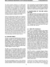
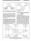
Distributed processing offers a faster, more powerful
system than can
be
provided by a single
CPU
processor.
This results from a hierarchy
of
interconnected
processors, each with its own memories and
1/
O.
In
multiprocessing, a host
8051
microcomputer controls a
multiplicity
of
8051
s configured to operate simultaneous-
lyon
separate portions
of
the program, each controlling a
portion
of
the overall process. The interconnected
8051
s
reduce the load on the host processor and result in a
low-
cost system
of
data transmission. This form
of
distributed
8
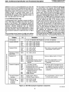
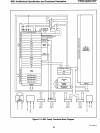
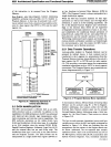
8051
DATA
CLOCK
PORT
PIN
A.1I0INPUT
EXPANSION
8051
DATA
CLOCK
PORT
PIN
B.
110
OUTPUT
EXPANSION
OS
EN
Figure 2.8. I/O Expansion Technique
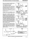
TTY
MODE
~~~--------~--~--~---'I~
TYPICAL
CRT
MULTI-
PROCESSOR
COMMUNICA-
TIONS
1/0
EXPANSION
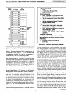
START
7-BIT
DATA
PARITY'
2
STOP
START
7·BIT
DATA MARK STOP
START 8-BIT
DATA
PARITY
STOP
START
a-BIT DATA
~~~:I
STOP
START
9-BIT DATA
STOP
j..DATA
....
------------'
__
ClK
a·BITS
Figure 2.9. Typical Frame Formats
,
2&3
2&3
o
AFN-01488A-12