


8051
Architectural Specification and Functional Description
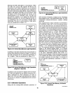
The process whereby a high-level interrupt request inter-
rupts a low-level interrupt service program
is
called
nesting. In this case the address
of
the next instruction
in the low-priority service program
is
pushed onto the
stack, the stack pointer
is
incremented by two
(2)
and
processor control
is
transferred to the Program Memory
location
of
the first instruction
of
the high-level service
program. The last instruction of the high-priority inter-
rupt service program must be an RETI instruction. This
instruction clears the higher
"priority-level-active" flip-
flop. RETI also returns processor control to the next
instruction
of
the low-level interrupt service program.
Since the lower "priority-level-active" flip-flop has
remained set, high priority interrupts are re-enabled
while further low priority interrupts remain disabled.
The highest-priority interrupt request gets serviced at the
end of the instruction-in-progress unless the request
is
made in the last fourteen oscillator periods
of
the
instruction-in-progress.
Under this circumstance, the next
instruction
will
also execute before the interrupt's sub-
routine call
is
made. The first instruction of the service
program will begin execution twenty-four oscillator
periods (the time required for the hardware subroutine
call) after
the
completion
of
the instruction-in-progress
or, under the circumstances mentioned earlier, twenty-
four oscillator periods after the next instruction .
.
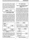
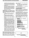
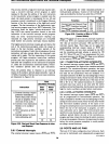
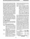
Thus, the greatest delay in response to an interrupt
request
is
86
oscillator periods (approximately 7
f.JSec
@
12
MHz). Examples
of
the best and worst case conditions
are illustrated in Figure 2.38.
Time
(Oscillator Periods)
Instruction
Best
Worst
Case
Case
1)
External interrupt request
2
+ E
2-E
generated immediately
before (best) / after (worst)
the pin
is
sampled. (Time
until end
of
bus cycle.)
2)
Current
or
next instruction
12
12
finishes in
12
oscillator
periods
3)
Next instruction
is
MUL don't
48
or
DIV
care
4)
Internal latency for hard-
24 24
ware subroutine call
38
86
Figure 2.38. Best and Worst Case Response
to
Inter-
rupt Request
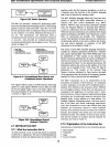
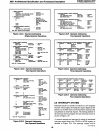
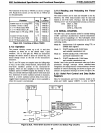
2.8.1 External Interrupts
The external interrupt request inputs
(INTO
and INTI)
24
can be programmed for either transition-activated or
level-activated operation. Control
of
the external inter-
rupts
is
provided
by
the four low-order bits of TCON.
Bit
Function Flag Location
External Interrupt Request Flag I
lEI
TCON.3
Input INTI Transition-Activated ITI TCON.2
External Interrupt Request Flag
0
lEO
TCON.I
Input
INTO
Transition Activated
ITO
TCON.O
Figure 2.39. Function
of
Bits in TCON
(Lower Nibble)
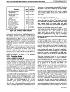
When
ITO
and IT I are set to one (I), interrupt requests on
INTO
and INTI are transition-activated (high-to-Iow);
else they are low-level activated.
lEO
and
lEI
are the
interrupt request flags. These flags are set when their
~sponding
interrupt request inputs
at
INTO
and
INTI,
respectively, are low when sampled
by
the
8051
and the transition-activated scheme
is
selected by
ITO
and ITI. When
ITO
and ITI are programmed for level-
activated interrupts, the
lEO
and IE I flags are not affected
by
the inputs
at
INTO
and INTI respectively.
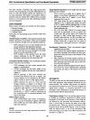
2.8.1.1
TRANSITION-ACTIVATED INTERRUPTS
The external. interrupt request inputs
(INTO
and INTI)
can be programmed for high-to-Iow transition-activated
.
operation. For transition-activated operation, the input
must remain low for greater than twelve oscillator periods,
but need not be synchronous with the oscillator.
It
is
internally latched
by
the
8051
near the falling-edge of ALE
during an instruction's tenth, twenty-second, thirty-fourth
and forty-sixth oscillator periods and, if the input
is
low,
lEO
or
lEI
is
set. The upward transition of a transition-
activated input may occur
at
any time after the twelve
oscillator period latching time, but the input must remain
high for twelve oscillator periods before reactivation.
2.8.1.2 LEVEL-ACTIVATED INTERRUPTS
The external interrupt request inputs
(INTO
and INTI)
can be programmed for level-activated operation. The
input
is
sampled by the
8051
near the falling-edge
of
ALE
during the instruction's tenth, twenty-second, thirty-fourth
and forty-sixth oscillator periods.
If
the input
is
low
during the sampling that occurs fourteen oscillator periods
before the end of
the"
instruction
in
progress, an inter-
rupt subroutine call
is
made. The level-activated input
need be low only during the sampling that occurs fourteen
oscillator periods before the end of the instruction-in-
progress and may remain
low during the entire execution
of the service program. However, the input must
be
raised
before the service program completes to
avoid possibly
envoking a second interrupt.
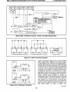
2.9 PORTS
AND
I/O
PINS
There are 32
I/O
pins configured as four 8-bit ports. Each
pin can
be
individually and independently programmed
AFN-01488A-28