


8051
Architectural Specification and Functional Description
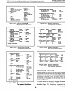
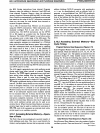
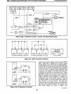
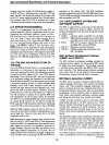
T1
___
--I
XTAL1
COUNTER 1
MODE 0: 8-BIT TIMER WITH PRESCALER/
8-BIT
COUNTER WITH PRESCALER
MODE
1:
16-BIT TIMER/COUNTER
MODE
2:
8·BIT
AUTO·RELOAD TIC
MODE 3: PREVENTS INCREMENTING
OF
TIC
COUNTER
0
PULSE TO
SERIAL PORT
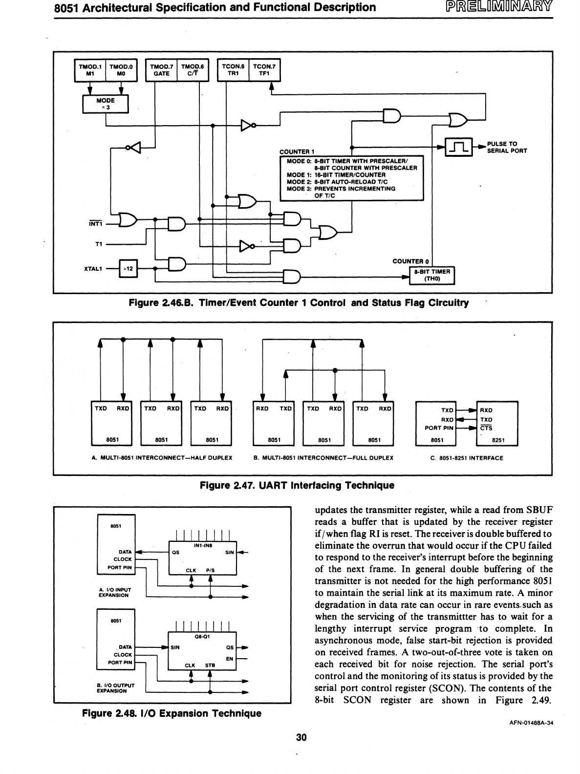
Figure 2.46.8. Timer/Event
Counter
1
Control
and Status Flag
Circuitry
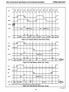
~
~
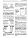
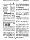
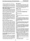
TXD RXD TXD RXD TXD RXD RXD TXD TXD
RXD
TXD
RXD
TXD
r----
RXD
RXD
~
TXD
PORT PIN
ffi
8051 8051
8051
8051
8051 8051 8051 8251
A.
MULTI·8051
INTERCONNECT-HALF
DUPLEX
B.
MULTI·8051
INTERCONNECT-FULL
DUPLEX
C.
8051·8251 INTERFACE
Figure 2.47.
UART
Interfacing Technique
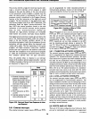
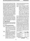
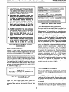
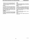
8051
DATA
14----1
CLOCK
PORT PIN
A.
IiOINPUT
EXPANSION
8051
.OATAt---
....
CLOCK
PORT PIN
B.
IiOOUTPUT
EXPANSION
SIN
as
EN
Figure 2.48.
I/O
Expansion Technique
30
updates the transmitter register, while a read from SBUF
reads a buffer that
is
updated by the receiver register
if / when flag RI
is
reset. The receiver
is
double buffered
to
eliminate the overrun that would occur
ifthe
CPU failed
to respond to the receiver's interrupt before the beginning
of the next frame. In general double buffering of the
transmitter
is
not needed for the high performance
8051
to maintain the serial link at its maximum rate. A minor
degradation in data rate can occur in rare events. such as
when the servicing of the transmittter has to wait for a
lengthy interrupt service program
to
complete. In
asynchronous mode, false start-bit rejection
is
provided
on received frames. A two-out-of-three vote
is
taken on
each received bit for noise rejection. The serial port's
control and the monitoring of its status
is
provided
by
the
serial port control register (SCON). The contents of the
8-bit SCON register are shown in Figure 2.49.
AFN·01488A·34