


8051 Architectural Specification and Functional Description
2.2.3.8 DATA POINTER
The 16-bit Data Pointer (DPTR) register
is
the concatina-
tion
of
registers
DPH
(data pointer's high-order byte) and
DPL
(data pointer's low-order byte). The
DPTR
is
used in
Register-Indire91 Addressing to move Program Memory
constants, to move External Data Memory variables, and
to branch over the 64K
Program Memory address space.
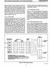
2.2.4 Arithmetic Section
The arithmetic section of the processor performs many
data
manipulation functions and
is
comprised
of
the
Arithmetic/Logic
Unit (ALU), A register, B register and
PSW register.
The AL
U accepts 8-bit data words from one or two
sources and generates
an
8-bit result under the control
of the instruction decoder. The
ALU performs the arith-
metic operations
of
add, subtract, multiply, divide, incre-
ment, decrement, BCD-decimal-add-adjust and compare
and .the logic operations of and, or, exclusive-or,
complement and rotate [right, left,
or
nibble swap (left
four)].
2.2.5 'Program Control Section
The program control section controls the sequence in
which the instructions stored in program memory are
executed. The conditional branch logic enables conditions
internal and external to the processor to cause a change
in the sequence of program execution.
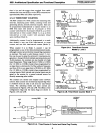
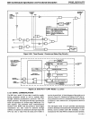
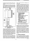
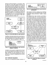
2.2.6 Oscillator and Timing Circuitry
Timing generation for the
8051
is
completely self-
contained, except for the frequency reference which can
be a crystal or external clock source. The on-board
oscillator
is
a parallel anti-resonant circuit with a
frequency range
of
1.2
to
12
MHz. The XTAL2 pin
is
the
output of a high-gain amplifier, while XT AL I
is
its input.
A crystal connected between XT AL I and XT AL2
provides the feedback and phase shift required for
oscillation. The
t.2 to
12
MHz range
is
also accomodated
when an external TTL compatible clock
is
applied to
XT AL 1 as the frequency source.
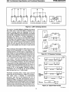
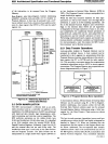
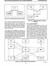
2.2.7 Boolean Processor
Although the Boolean processor
is
an integral part of the
8051's architecture, it may
be
considered an independent
bit processor since it has its own instruction set, its own
accumulator (the carry flag), and its own bit-addressable
RAM and
I/O.
The bit-manipulation instructions allow the Direct
Addressing of
128
bits within the Internal
Data
RA M
and
128
bits within the Special Function Registers. The
Special Function Registers with an address evenly
divisable
by
eighqpO, TCON,
PI,
SCON, P2, IEC, P3,
IPC, PSW,
A.
and
B)
contain Direct Addressable bits.
11
On any addressable bit, the Boolean processor can per-
form the bit operations of set, clear, complement,
jump-if-set, jump-if-not-set,
j~mp-if-set-then-clear
and
move to/from carry. Between any addressable bit (or its
complement) and the carry flag
it
can perform the bit
operation of logical and or logical
or
with the result
returned to the carry flag.
The bit-manipulation instructions provide optimum code
and speed efficiency in
"bit-banging" applications such as
the control of the
8051's on-chip peripherals. The Boolean
processor also provides a straightforward means of con-
verting
logic
equations
(like
those
used in
random
logic design) directly into software. Complex combina-
torial-logic functions can be resolved without extensive
data movement, byte masking and test-and-branch trees.
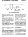
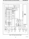
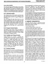
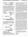
2.3
MEMORY
ORGANIZATION
In the
8051
family the memory
is
organized ever three
address spaces and the program counter. The memory
spaces shown in Figure
2.1
are the:
• 16-bit Program Counter
• 64K-byte Program Memory address space
• 64K-byte External Data Memory address space
• 384-byte Internal Data Memory address space
The 16-bit
Program Counter register provides the
8051
with its 64K addressing capabilities. The Program Counter
allows the user to execute calls and branches
to
any loca-
tion within the
Program Memory space. There are no
instructions that permit program execution to move from
the
Program Memory space to any of the data memory
spaces.
In the
8051
and
8751
the lower 4K of the 64K Program
Memory address space
is
filled by internal ROM and
EPROM,
respectively.
By
trying the EA pin high, the
processor can be forced to fetch from the internal
ROM/EPROM
for Program Memory addresses 0
through 4K. Bus expansion for accessing Program
Memory beyond 4K
is
automatic since external in-
struction fetches occur automatically when the
Program
Counter increases above 4095.
If
the EA pin
is
tied low all
Program Memory fetches are from external memory.
The execution speed of the
8051
is
an same regardless
of
whether fetches are from internal
or
external Program
Memory. If all program storage
is
on-chip, byte location
4095
should
be left
vacant
to
prevent
an
undesired
prefetch from external Program Memory address 4096.
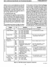
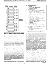
Certain locations in
Program Memory are reserved for
specific programs. Locations
0000 through
0002
are
reserved for the initialization program. Following reset,
the
CPU always begins execution at location 0000.
Locations
0003
through 0042 are reserved for the
five
interrupt-request service programs. Each resource that
can request an interrupt requires that its service program
be
stored at its reserved location.
AFN-01488A-15