


8051
Architectural Specification and Functional Description
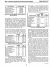
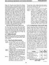
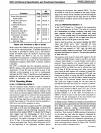
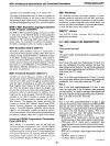
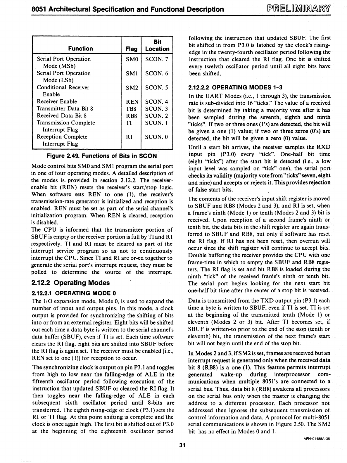
Bit
Function
Flag
Location
Serial Port Operation
SMO
SCON.7
Mode (MSb)
Serial
Port Operation
SMI
SCON.6
Mode (LSb)
Conditional Receiver
SM2
SCON.5
Enable
Receiver Enable
REN
SCON.4
Transmitter Data Bit 8
TB8
SCON.3
Received Data
Bit
8
RB8
SCON.2
Transmission Complete
TI
SCON. I
Interrupt Flag
Reception Complete
RI
SCON.O
Interrupt Flag
Figure 2.49. Functions
of
Bits
in
SCaN
Mode control hits S
MO
and
S M I program the serial port
in one
of
four operating modes. A detailed description
of
the modes
is.
provided in section 2.12.2. The receiver-
enable bit (REN) resets the receiver's start/stop logic.
When software sets REN to one
(1), the receiver's
transmission-rate generator
is
initialized and reception
is
enabled. REN must be set as part
of
the serial channel's
initialization program. When REN
is
cleared, reception
is
disabled.
The
CPU
is
informed
that
the transmitter portion .of
SB
UF
is
empty
or
the receiver portion
is
full by TI
and
RI
respectively. TI and RI must
be
cleared as part
of
the
interrupt service program so as not to continuously
interrupt the
CPU. Since TI and RI are or-ed together to
generate the serial port's interrupt request, they must
be
polled to determine· the source
of
the interrupt.
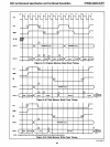
2.12.2 Operating Modes
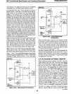
2.12.2.1
OPERATING MODE 0
The
1/0
expansion mode, Mode 0,
is
used to expand the
number
of
input and output pins. In this mode, a clock
output
is
provided for synchronizing the shifting
of
bits
into or from
an
external register. Eight bits
will
be
shifted
out each time a
data
byte
is
written to the serial channel's
data buffer (SBUF), even if TI
is
set. Each time software
clears the RI flag, eight bits are shifted into
SBUF before
the RI flag
is
again set. The receiver must
be
enabled [i.e.,
REN set to one (I)] for reception to occur.
The synchronizing clock is output
on
pin P3.1
and
toggles
from high to low near the falling-edge
of
ALE in the
fifteenth oscillator period following execution
of
the
instruction
that
updated SBUF
or
cleared the RI flag.
It
then toggles near the falling-edge
of
ALE in each
subsequent sixth oscillator period until 8-bits are
transferred. The eighth rising-edge of clock
(P3.1) sets the
RI or TI flag. At this point shifting
is
complete and the
clock
is
once again high. The first bit
is
shifted out
of
P3. 0
at the beginning
of
the eighteenth oscillator period
31
following the instruction that updated SBUF. The first
bit shifted in from
P3.0
is
latohed by the clock's rising-
edge
in
the twenty-fourth oscillator period following the
instruction
that
cleared the RI flag. One bit
is
shifted
every twelvth oscillator period until all eight bits have
been shifted.
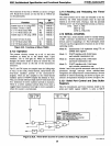
2.12.2.2 OPERATING MODES
1-3
In the
UART
Modes (i.e., I through 3), the transmission
rate
is
sub-divided into
16
"ticks." The value
of
a received
bit
is
determined by taking a majority vote after it has
been sampled during the seventh, eighth and
ninth
"ticks".
If two
or
three ones (I's) are detected, the bit will
be given a one
(I)
value; if two
or
three zeros
(O's)
are
detected, the bit will be given a zero (0) value.
Until a start bit arrives, the receiver samples the
RXD
input pin (P3.0) every "tick". One-half bit time
(eight "ticks") after the start bit
is
detected (i.e., a low
input level was sampled on
"tick" one), the serial port
checks its validity (majority vote from
"ticks" seven, eight
and
nine) and accepts
or
rejects it. This provides rejection
of
false start bits.
The contents
of
the receiver's input shift register
is
moved
to SBUF and RB8 (Modes 2 and
3),
and RI
is
set, when
a frame's ninth (Mode
1)
or
tenth (Modes 2 and
3)
bit
is
received. Upon reception
of
a second frame's ninth
or
tenth bit, the
data
bits in the shift register are again trans-
ferred to
SBUF and RB8, but only if software has reset
the RI flag.
If
RI has not been reset, then overrun
will
occur since the shift register
will
continue to accept bits.
Double buffering the receiver provides the
CPU with one
frame-time in which to empty the SBUF and
RB8
regis-
ters. The RI flag
is
set and bit RB8
is
loaded during the
ninth
"tick"
of
the received frame's ninth
or
tenth bit.
The serial port begins looking for the next start bit
one-half bit time after the center of a stop bit
is
received.
Data
is
transmitted from the
TXD
output pin (P3.1) each
time a byte
is
written to SBUF, even if TI
is
set. TI
is
set
at
the beginning
of
the transmitted tenth (Mode
1)
or
eleventh (Modes 2 or
3)
bit. After TI becomes set, if
SBUF
is
written-to prior to the end
of
the stop (tenth
or
eleventh) bit, the transmission
of
the next frame's
start.
bit
will
not begin until the end
of
the stop bit.
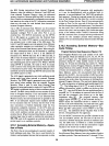
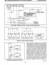
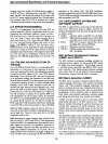
In Modes 2 and 3,
ifSM2isset,
frames are received
but
an
interrupt request is generated only when the received
data
bit 8 (RB8)
is
a one (1). This feature permits interrupt
generated wake-up during interprocessor com-
munications when mUltiple
8051
's are connected
to
a
serial bus. Thus,
data
bit 8 (RB8) awakens all processors
on
the serial bus only when the master
is
changing the
address to a different processor. Each processor not
addressed then ignores the subsequent transmission
of
control information and data. A protocol for multi-80S I
serial communications
is
shown in Figure 2.50. The SM2
bit has no effect in Modes
0 and
l.
AFN-01488A-35