


8051
Architectural Specification and Functional Description
The Data Transfer, Arithmetic and Logic groups men-
tioned in the preceding list are further subdivided into an .
array
of
codes that specify whether the operation
is
to
act upon immediate, RB register, accumulator,
SFR
or
memory locations; whether bits, nibbles, bytes or double-
bytes are to be processed; and what addressing methods
are to be employed.
DATA
TRANSFER
.
Data
transfer operations are divided into three classes:
• General Purpose
• Accumulator-Specific
• Address-Object
None affect the flag settings except a
POP
or MOV into
the
PSW.
~~~:·~~·.;·1'··:
...
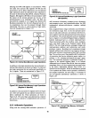
General Purpose Transfers. Three general purpose
data
transfer operations are provided. These may be applied
to most operands, though there are specific exceptions.
MOV performs a bit or a byte transfer from the
source operand to the destination operand.
PUSH increments the
SP
register and then trans-
fers a byte from the source operand to the stack
element currently addressed by
SP.
POP
transfers a byte operand from the stack
element addressed
by
the
SP
register to the
destination operand and then decrements
SP.
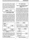
Accumulator-Specific Transfers. Four accumulator-specific
transfer operations are provided:
XCH exchanges the byte source operand with
register A (accumulator).
XCHD
exchanges the low-order nibble
of
the
byte source operand with the low-order nibble of
register
A.
MOVX performs a byte move between the
External Data Memory and the A register. The
external address can be specified by the
DPTR
register (16-bit)
or
the
Rl
or
RO
register (8-bit).
MOVC performs the move of a byte from the
Program Memory to register A as follows. The
operand in the A register
is
used as an index into
a 256-byte table pointed to by the base register
(DPTR
or PC). The byte operand accessed
is
transferred to
A.
MOVC
is
used for table-look-up
byte translation and for accessing operands from
code-in-line tables.
Address-Object Transfer
MOV DPTR,#data loads 16-bits of immediate
data into a pair of destination registers,
DPH
and
DPL
(DPH from low-order address,
DPL
from
high-order address).
LOGIC
The
8051
performs the basic logic operations on both bit
and byte operands.
19
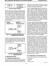
Single-Operand Operations. Seven single-operand logical
operations are provided:
CLR
is
used to set eitber the A register, the C
register, or any Direct Addressed bit
to
zero
(0).
SETB sets either the C register
or
any Direct
Addressed bit to one
(1).
CPL
either forms the one's complement
of
the
operand in the A register and returns the result
to the A register without affecting flags or forms
the one's complement
of
the C register or any
Direct Addressed bit.
RL, RLC, RR, RRC,
SWAP. Five rotate opera-
tions can be performed on the A register; RL
(rotate left), RR (rotate right), RLC (rotate left
through C), RRC (rotate right through C) and
SW
AP
(rotate left four).
For
RLC and RRC the C
flag becomes equal to the last bit rotated out.
SWAP rotates the A register left four places to
exchange bits 3 through
0 with bits 7 through
4.
Two-Operand Operations. Three two-operand logical
operations are provided:
ANL performs the bitwise logical conjunction
of
two source operands (for both bit and byte oper-
ands) and returns the result to the location
of
the
first operand.
ORL
performs the bitwise logical inclusive dis-
junction
of
two source operands (for both bit and
byte operands) and returns the result to the
loca-
tion
of
the first operand.
XRL performs the bitwise logical exclusive
disjunc-
tion of the two source oPerands (byte operands)
and returns the result to the location of the first
operand.
ARITHMETIC
The
8051
provides the four basic mathematical operations.
Only 8-bit operations using unsigned arithmetic are sup-
ported directly. The overflow flag permits the addition
and subtraction operations to serve for both unsigned and
signed binary integers. A correction operation
is
also
provided to allow arithmetic to
be
peiformed directly on
packed decimal (BCD) representations.
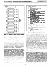
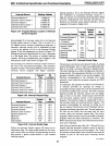
Flag Register
Settings. Three one-bit flag registers are set
or cleared by arithmetic operations to
refl\!ct certain
properties of the result of the operation. These flags are
not affected
by
the increment and decrement instruc-
tions. A fourth flag (P) denotes the parity
of
the eight
accumulator bits. These flag registers are located in the
Program
Status Word (PSW) register. Their bit assign-
ment are shown below. A list of the instructions that
affect these flags
is
provided in the
"8051
Instruction Set
Summary"
in Table 2-\' .
AFN-01488A-23