


154
CHAPTER 6 PORT FUNCTIONS
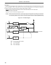
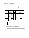
(3) Memory expansion mode register (MM)
This register is used to set input/output of port 4.
MM is set with a 1-bit or 8-bit memory manipulation instruction.
RESET input sets this register to 10H.
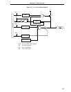
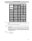
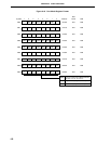
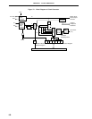
Figure 6-21. Memory Expansion Mode Register Format
Note The full address mode allows external expansion for all areas of the 64-Kbyte address space,
except the internal ROM, RAM, SFR, and use-prohibited areas.
Remarks 1. P60 to P63 pins enter the port mode in both the single-chip and memory expansion mode.
2. Besides setting port 4 input/output, MM also sets the wait count and external expansion area.
0 0 PW1 0MM FFF8H 10H R/W
765432Symbol Address
After
Reset R/W
1
PW0 MM2 MM1 MM0
0
MM2 MM1 MM0
000
001
011
100
101
111
Other than above
Setting prohibited
Single-chip/Memory
Expansion Mode
Selection
Single-chip mode
256-byte
mode
4-Kbyte
mode
16-Kbyte
mode
Full
Note
address
mode
Memory
expansion
mode
AD0-AD7
Input
Out-
put
Port
mode
P40-P47
P40-P47, P50-P57, P64-P67 Pin State
PW1
PW0
0
0
0
1
1
1
0
1
Wait Control
No wait
Wait (one wait state insertion)
Setting prohibited
Wait control by external wait pin
P56, P57 P64-P67
Port mode
Port mode
Port mode
Port mode
A14, A15
A12, A13
P64=RD
P65=WR
P66=WAIT
P67=ASTB
P50-P53 P54, P55
A8-A11