


207
CHAPTER 8 16-BIT TIMER/EVENT COUNTER
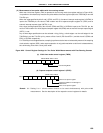
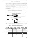
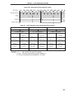
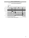
Count Clock
TM0 Count Value
CR00
INTTM0
TO0 Pin Output
0000 0001 0002 N-1 N 0000 0001 0002 N-1 N 0000
N
Figure 8-30. Square-Wave Output Operation Timing
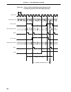
Table 8-7. 16-Bit Timer/Event Count Square-Wave Output Ranges
Minimum Pulse Width Maximum Pulse Width Resolution
MCS = 1 MCS = 0 MCS = 1 MCS = 0 MCS = 1 MCS = 0
2 × TI00 input cycle 2
16
× TI00 input cycle TI00 input edge cycle
2 × 1/fX 2
16
× 1/fX 1/fX
(400 ns) (13.1 ms) (200 ns)
2 × 1/fX 2
2
× 1/fX 2
16
× 1/fX 2
17
× 1/fX 1/fX 2 × 1/fX
(400 ns) (800 ns) (13.1 ms) (26.2 ms) (200 ns) (400 ns)
2
2
× 1/fX 2
3
× 1/fX 2
17
× 1/fX 2
18
× 1/fX 2 × 1/fX 2
2
× 1/fX
(800 ns) (1.6
µ
s) (26.2 ms) (52.4 ms) (400 ns) (800 ns)
2
3
× 1/fX 2
4
× 1/fX 2
18
× 1/fX 2
19
× 1/fX 2
2
× 1/fX 2
3
× 1/fX
(1.6
µ
s) (3.2
µ
s) (52.4 ms) (104.9 ms) (800 ns) (1.6
µ
s)
2 × watch timer output cycle 2
16
× watch timer output cycle Watch timer output edge cycle
Remarks 1. fX : Main system clock oscillation frequency
2. MCS : Oscillation mode selection register (OSMS) bit 0
3. Values in parentheses when operated at fX = 5.0 MHz
———