


484
CHAPTER 21 INTERRUPT AND TEST FUNCTIONS
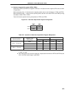
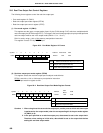
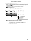
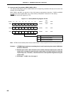
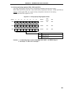
21.2 Interrupt Sources and Configuration
Interrupt sources includes total of 22 non-maskbale, maskable, software interrupts (refer to Table 21-1).
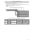
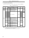
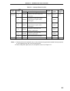
Table 21-1. Interrupt Source List (1/2)
Interrupt Source
Name Trigger
Watchdog timer overflow (with
watchdog timer mode 1 selected)
Watchdog timer overflow (with
interval timer mode selected)
1 INTP0 0006H (C)
2 INTP1 0008H
3 INTP2 000AH
4 INTP3 Pin input edge detection External 000CH (D)
5 INTP4 000EH
6 INTP5 0010H
7 INTP6 0012H
End of serial interface channel 0
transfer
End of serial interface channel 1
transfer
Serial interface channel 2 UART reception
error generation
End of serial interface channel 2
UART reception
End of serial interface channel 2
3-wire transfer
End of serial interface channel 2
UART transfer
0 INTWDT (B)
8 INTCSI0 0014H
9 INTCSI1 0016H
10 INTSER 0018H
11
001AH
INTSR
INTCSI2
12 INTST 001CH
Interrupt
Type
Default
Priority
Internal/
External
Vector
Table
Address
Basic
Configuration
Type
Note 1
Note 2
Non-
maskable
Internal
Internal
(B)
Notes 1. Default priorities are intended for two or more simultaneously generated maskable interrupt requests.
0 is the highest priority and 20 is the lowest priority.
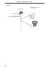
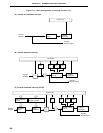
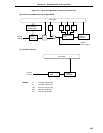
2. Basic configuration types (A) to (E) correspond to (A) to (E) of Figure 21-1.
Maskable
– INTWDT (A)
0004H