


236
CHAPTER 9 8-BIT TIMER/EVENT COUNTERS 1 AND 2
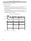
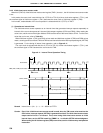
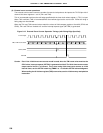
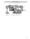
(2) External event counter operations
The external event counter counts the number of external clock pulses to be input to the TI1/P33 pin with 2-
channel 8-bit timer registers 1 and 2 (TM1 and TM2).
TM1 is incremented each time the valid edge specified with the timer clock select register 1 (TCL1) is input.
When TM1 overflows, TM2 is incremented with the overflow signal as the count clock. Either the rising or
falling edge can be selected.
When the TM1 and TM2 counted values match the values of 8-bit compare registers 10 and 20 (CR10 and
CR20), TM1 and TM2 are cleared to 0 and the interrupt request signal (INTTM2) is generated.
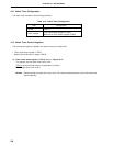
Figure 9-12. External Event Counter Operation Timings (with Rising Edge Specified)
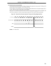
Caution Even if the 16-bit timer/event counter mode is used, when the TM1 count value matches the
CR10 value, interrupt request (INTTM1) is generated and the F/F of 8-bit timer/event counter
output control circuit 1 is inverted. Thus, when using 8-bit timer/event counter as 16-bit
interval timer, set the INTTM1 mask flag TMMK1 to 1 to disable INTTM1 acknowledgment.
When reading the 16-bit timer register (TMS) count value, use the 16-bit memory manipulation
instruction.
TI1 Pin Input
TM1, TM2 Count Value
CR10, CR20
INTTM2
0000 0001 0002 0003 0004 0005 N-1 N 0000 0001 0002 0003
N