


480
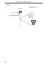
CHAPTER 20 REAL-TIME OUTPUT PORT
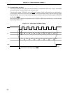
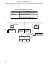
20.3 Real-Time Output Port Control Registers
The following three registers control the real-time output port.
• Port mode register 12 (PM12)
• Real-time output port mode register (RTPM)
• Real-time output port control register (RTPC)
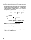
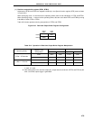
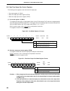
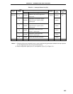
(1) Port mode register 12 (PM12)
This register sets the input or output mode of port 12 pins (P120 through P127) which are multiplexed with
real-time output pins (RTP0 through RTP7). To use port 12 as a real-time output port, the port pin that performs
real-time output must be set in the output mode (PM12n = 0: n = 0 to 7).
PM12 is set by using a 1-bit or 8-bit memory manipulation instruction.
This register is set to FFH by RESET input.
Figure 20-3. Port Mode Register 12 Format
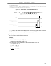
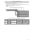
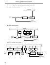
(2) Real-time output port mode register (RTPM)
This register selects the real-time output port mode/port mode bit-wise.
RTPM is set with a 1-bit or 8-bit memory manipulation instruction.
RESET input sets this register to 00H.
Figure 20-4. Real-time Output Port Mode Register Format
Cautions 1. When using these bits as a real-time output port, set the ports to which real-time output
is performed to the output mode (clear the corresponding bit of the port mode register
12 (PM12) to 0).
2. In the port specified as a real-time output port, data cannot be set to the output latch.
Therefore, when setting an initial value, data should be set to the output latch before
setting the real-time output mode.
7
RTPM7
6
RTPM6
5
RTPM5
4
RTPM4
3
RTPM3
2
RTPM2
1
RTPM1
0
RTPM0
Symbol
RTPM
Address
FF34H 00H
After
Reset
R/W
R/W
RTPMn
0
1
Port mode
Real-time Output Port Mode
Real-time Output Port Selection (n = 0 to 7)
7
PM127
6
PM126
5
PM125
4
PM124
3
PM123
2
PM122
1
PM121
0
PM120
Symbol
PM12
Address
FF2CH
After Reset
FFH
R/W
R/W
PM12n
0
1
Output mode (output buffer ON)
Input mode (ourput buffer OFF)
Selects I/O mode of P12n pin (n = 0 to 7)