


277
CHAPTER 14 A/D CONVERTER
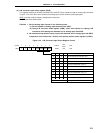
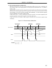
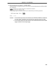
(2) A/D conversion operation in software start
When bit 6 (TRG) and bit 7 (CS) of A/D converter mode register (ADM) are set to 0 and 1, respectively, the
A/D conversion starts on the voltage applied to the analog input pins specified with bits 1 to 3 (ADM1 to
ADM3) of ADM.
Upon termination of the A/D conversion, the conversion result is stored in the A/D conversion result register
(ADCR) and the interrupt request signal (INTAD) is generated. After one A/D conversion operation is started
and terminated, the next A/D conversion operation starts immediately. The A/D conversion operation
continues repeatedly until new data is written to ADM.
If data with CS set to 1 is written to ADM again during A/D conversion, the converter suspends its A/D
conversion operation and starts A/D conversion on the newly written data.
If data with CS set to 0 is written to ADM during A/D conversion, the A/D conversion operation stops
immediately.
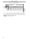
Figure 14-9. A/D Conversion by Software Start
Remarks 1. n = 0, 1, ... , 7
2. m = 0, 1, ... , 7
Conversion Start
CS=1, TRG=0
A/D Conversion
ADCR
INTAD
ANIn ANIn ANIm
ANIn ANIm ANImANInANIn
ADM Rewrite
CS=1, TRG=0
ADM Rewrite
CS=0, TRG=0
Conversion suspended
Conversion results are
not stored
Stop