


450
CHAPTER 19 SERIAL INTERFACE CHANNEL 2
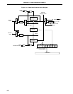
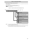
The baud rate transmit/receive clock generated is either a signal scaled from the main system clock, or a signal
scaled from the clock input from the ASCK pin.
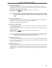
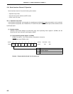
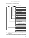
(a) Generation of baud rate transmit/receive clock by means of main system clock
The transmit/receive clocks generated by scaling the main system clock. The baud rate generated from
the main system clock is found from the following expression.
[Baud rate] = [Hz]
where, f
X : Main system clock oscillation frequency
fXX : Main system clock frequency (fx or fx/2)
n : Value set in TPS0 to TPS3 (1 ≤ n ≤ 11)
k : Value set in MDL0 to MDL3 (0 ≤ k ≤ 14)
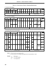
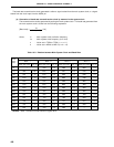
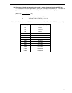
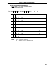
Table 19-3. Relation between Main System Clock and Baud Rate
fx = 5.0 MHz fx = 4.19 MHz
MCS = 1 MCS = 0 MCS = 1 MCS = 0
BRGC Set Value Error (%) BRGC Set Value Error (%) BRGC Set Value Error (%) BRGC Set Value Error (%)
75 – 00H 1.73 0BH 1.14 EBH 1.14
110 06H 0.88 E6H 0.88 03H –2.01 E3H –2.01
150 00H 1.73 E0H 1.73 EBH 1.14 DBH 1.14
300 E0H 1.73 D0H 1.73 DBH 1.14 CBH 1.14
600 D0H 1.73 C0H 1.73 CBH 1.14 BBH 1.14
1200 C0H 1.73 B0H 1.73 BBH 1.14 ABH 1.14
2400 B0H 1.73 A0H 1.73 ABH 1.14 9BH 1.14
4800 A0H 1.73 90H 1.73 9BH 1.14 8BH 1.14
9600 90H 1.73 80H 1.73 8BH 1.14 7BH 1.14
19200 80H 1.73 70H 1.73 7BH 1.14 6BH 1.14
31250 74H 0 64H 0 71H –1.31 61H –1.31
38400 70H 1.73 60H 1.73 6BH 1.14 5BH 1.14
76800 60H 1.73 50H 1.73 5BH 1.14 — —
Remark MCS: Oscillation mode selection register bit 0
fXX
2
n
× (k+16)
Baud
Rate
(bps)