


479
CHAPTER 20 REAL-TIME OUTPUT PORT
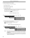
Operating Mode
Register to be
Manipulated
4 Bits × 2 Channels
8 Bits × 1 Channel
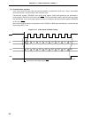
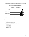
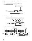
(1) Real-time output buffer register (RTBL, RTBH)
Addresses of RTBL and RTBH are mapped individually in the Special function register (SFR) area as shown
in Figure 20-2.
When specifying 4 bits × 2 channels as the operating mode, data are set individually in RTBL and RTBH.
When specifying 8 bits × 1 channel as the operating mode, data are set to both RTBL and RTBH by writing
8-bit data to either RTBL or RTBH.
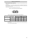
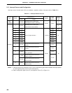
Table 20-2 shows operations during manipulation of RTBL and RTBH.
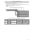
Figure 20-2. Real-time Output Buffer Register Configuration
Table 20-2. Operation in Real-time Output Buffer Register Manipulation
In Read
Note1
In Write
Note2
Higher 4 Bits Lower 4 Bits Higher 4 Bits Lower 4 Bits
RTBL RTBH RTBL Invalid RTBL
RTBH RTBH RTBL RTBH Invalid
RTBL RTBH RTBL RTBH RTBL
RTBH RTBH RTBL RTBH RTBL
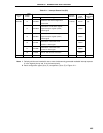
Notes 1. Only the bits set in the real-time output port mode can be read. When a bit set in the port mode
is read, 0 is read.
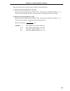
2. After setting data in the real-time output port, output data should be set in RTBL and RTBH by the
time a real-time output trigger is generated.
Higher
4 Bits
Lower
4 Bits
RTBL
RTBH
FF30H
FF31H