


324
CHAPTER 16 SERIAL INTERFACE CHANNEL 0 (
µ
PD78054 Subseries)
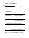
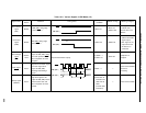
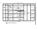
Timing ChartDefinitionSignal Name
Output
Device
Output
Condition
Effects on Flag Meaning of Signal
Synchronous clock to
output address/command/
data, ACK signal,
synchronous BUSY signal,
etc. Address/command/
data are transferred with
the first eight synchronous
clocks.
8-bit data to be transferred
in synchronization with
SCK0 after output of only
CMD signal without REL
signal output
Master
Numeric values to be
processed with slave
or master device
Serial clock
(SCK0)
Timing of signal
output to serial data
bus
Address value of
slave device on the
serial bus
Address
(A7 to A0)
8-bit data to be transferred
in synchronization with
SCK0 after output of REL
and CMD signals
Master
Commands
(C7 to C0)
Instructions and
messages to the
slave device
Master/
slave
Data
(D7 to D0)
8-bit data to be transferred
in synchronization with
SCK0 without output of
REL and CMD signals
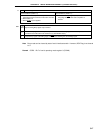
Table 16-3. Various Signals in SBI Mode (2/2)
When CSIE0 = 1,
execution of
instruction for
data write to
SIO0 (serial
transfer start
instruction)
Note 2
Notes 1. When WUP = 0, CSIIF0 is set at the rising edge of the 9th clock of SCK0.
When WUP = 1, an address is received. Only when the address matches the slave address register (SVA) value, CSIIF0 is set. (if the address does
not coincide with the value of SVA, RELD is cleared).
2. In BUSY state, transfer starts after the READY state is set.
Master
CSIIF0 set (rising
edge of 9th clock
of SCK0)
Note 1
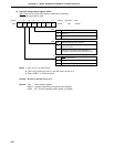
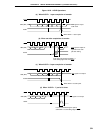
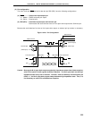
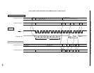
SCK0
SB0 (SB1)
1278910
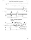
SCK0
SB0 (SB1)
1278
REL CMD
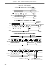
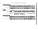
SCK0
SB0 (SB1)
1278
CMD
SCK0
SB0 (SB1)
1278