


434
CHAPTER 18 SERIAL INTERFACE CHANNEL 1
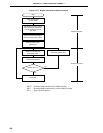
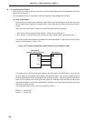
(c) Bit Slippage Detection Function Through the Busy Signal
During an auto send and receive operation, noise occur in the serial clock signal output by the master
device and bit slippage may occur in the slave device side serial clock. At this time, if the strobe control
option is not used, this bit slippage will have an effect on sending of the next byte. In such a case, the
busy control option can be used on the master device side and, by checking the busy signal during sending,
bit slippage can be detected.
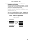
Bit slippage detection through the busy signal is accomplished as follows.
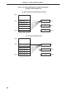
The slave side outputs a busy signal after the serial clock rises on the 8th cycle of data sending or receiving
(at this time, if application of the wait state by the busy signal is not desired, the busy signal is made inactive
within 2 clock cycles).
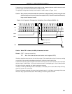
The master device side samples the busy signal in sync with the fall of the serial clock’s front side. If
no bit slippage is occurring, the busy signal will be inactive in sampling for 8 clock cycles. If the busy
signal is found to be active in sampling, it is regarded as an occurrence of bit slippage error processing
is executed (bit 4 (ERR) of the auto data send and receive control register (ADTC) is set at (1)).
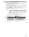
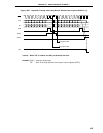
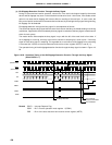
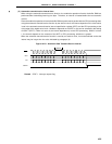
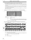
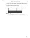
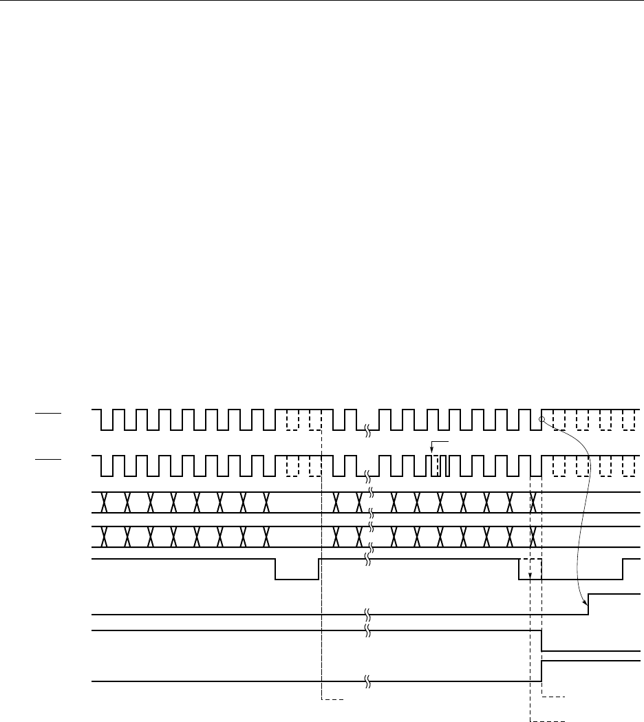
The operation timing of the bit slippage detection function through the busy signal is shown in Figure 18-
22.
Figure 18-22. Operation Timing of the Bit Slippage Detection Function Through the Busy SIgnal
(when BUSY0 = 1)
Remark CSIIF1 : Interrupt Request Flag
CSIE1 : Bit 7 of serial operation mode register 1 (CSIM1)
ERR : Bit 4 of the auto data send and receive control register (ADTC)
Error Interrupt
Request Generation
SCK1
SCK1
SO1
D7 D6 D5 D4 D3 D2 D1 D0 D7 D7 D6 D5 D4 D3 D2 D1
BUSY
CSIIF1
SI1 D7 D6 D5 D4 D3 D2 D1 D0 D7 D7 D6 D5 D4 D3 D2 D1
CSIE1
No Busy Detection
ERR
D0
D0
Error Detection
Bit Slippage Due to Noise
(Slave Side)
(Master Side)