


226
CHAPTER 9 8-BIT TIMER/EVENT COUNTERS 1 AND 2
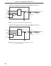
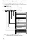
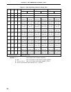
(3) 8-bit timer output control register (TOC1)
This register controls operation of 8-bit timer/event counter output control circuits 1 and 2.
It sets/resets the R-S flip-flops (LV1 and LV2) and enables/disables inversion and 8-bit timer output of 8-bit
timer registers 1 and 2.
TOC1 is set with a 1-bit or 8-bit memory manipulation instruction.
RESET input sets TOC1 to 00H.
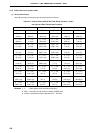
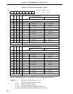
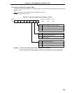
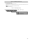
Figure 9-6. 8-Bit Timer Output Control Register Format
Cautions 1. Be sure to set TOC1 after stopping timer operation.
2. After data setting, 0 can be read from LVS1, LVS2, LVR1 and LVR2.
<0>1<2><3><4>5<6><7>Symbol
TOE1TOC11LVR1LVS1TOE2TOC15LVR2LVS2TOC1
FF4FH 00H R/W
Address After Reset R/W
TOE1
8-Bit Timer/Event Counter 1 Outptut Control
0
Output disable (port mode)
1
Output enable
TOC11 8-Bit Timer/Event Counter 1 Timer Output F/F Control
0 Inverted operation disable
1 Inverted operation enable
LVS1 LVR1
8-Bit Timer/Event Counter 1 Timer Output F/F Status Set
0 0 Unchanged
0 1 Timer output F/F reset (0)
1 0 Timer output F/F set (1)
1 1 Setting prohibited
TOE2 8-Bit Timer/Event Counter 2 Output Control
0 Output disable (port mode)
1 Output enable
TOC15 8-Bit Timer/Event Counter 2 Timer Output F/F Control
0 Inverted operation disable
1 Inverted operation enable
LVS2 LVR2
8-Bit Timer/Event Counter 2 Timer Output F/F Status Set
0 0 Unchanged
0 1 Timer output F/F reset (0)
1 0 Timer output F/F set (1)
1 1 Setting prohibited