


33
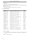
LIST OF TABLES (1/3)
Table No. Title Page
1-1. Differences between Standard Quality Grade Products and (A) Products.................................... 48
1-2. Mask Options of Mask ROM Versions...........................................................................................48
2-1. Mask Options of Mask ROM Versions...........................................................................................58
3-1. Pin Input/Output Circuit Types....................................................................................................... 71
4-1. Pin Input/Output Circuit Types....................................................................................................... 87
5-1. Internal ROM Capacity .................................................................................................................. 99
5-2. Vector Table................................................................................................................................... 99
5-3. Internal High-Speed RAM Capacity .............................................................................................. 100
5-4. Internal High-Speed RAM Area ..................................................................................................... 110
5-5. Correspondent Table of Absolute Addresses in the General Registers......................................... 112
5-6. Special-Function Register List....................................................................................................... 115
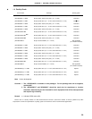
6-1. Port Functions (
µ
PD78054 subseries) .......................................................................................... 130
6-2. Port Functions (
µ
PD78054Y subseries) ........................................................................................ 132
6-3. Port Configuration ......................................................................................................................... 134
6-4. Pull-up Resistor of Port 6 .............................................................................................................. 144
6-5. Port Mode Register and Output Latch Settings when Using Dual-Functions ................................ 151
6-6. Comparison between Mask ROM Version and PROM Version..................................................... 157
7-1. Clock Generator Configuration ...................................................................................................... 159
7-2. Relationship between CPU Clock and Minimum Instruction Execution Time................................ 163
7-3. Maximum Time Required for CPU Clock Switchover .................................................................... 172
8-1. Timer/Event Counter Operations ................................................................................................... 176
8-2. 16-Bit Timer/Event Counter Interval Times.................................................................................... 177
8-3. 16-Bit Timer/Event Counter Square-Wave Output Ranges ........................................................... 178
8-4. 16-Bit Timer/Event Counter Configuration..................................................................................... 179
8-5. INTP0/TI00 Pin Valid Edge and CR00 Capture Trigger Valid Edge .............................................. 181
8-6. 16-Bit Timer/Event Counter Interval Times.................................................................................... 193
8-7. 16-Bit Timer/Event Count Square-Wave Output Ranges .............................................................. 207
9-1. 8-Bit Timer/Event Counters 1 and 2 Interval Times ....................................................................... 216
9-2. 8-Bit Timer/Event Counters 1 and 2 Square-Wave Output Ranges .............................................. 217
9-3. Interval Times when 8-Bit Timer/Event Counters 1 and 2 are Used as
16-Bit Timer/Event Counters ......................................................................................................... 218
9-4. Square-Wave Output Ranges when 8-Bit Timer/Event Counters 1 and 2 are Used as
16-Bit Timer/Event Counters ......................................................................................................... 219
9-5. 8-Bit Timer/Event Counters 1 and 2 Configurations ...................................................................... 220
9-6. 8-Bit Timer/Event Counter 1 Interval Time .................................................................................... 229
9-7. 8-Bit Timer/Event Counter 2 Interval Time .................................................................................... 230