


538
CHAPTER 25 ROM CORRECTION
FF3AH/FF3BH 0000H
Symbol 15
CORAD0
0 Address
FF38H/FF39H
State
after reset
0000H
R/W
R/W
CORAD1 R/W
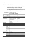
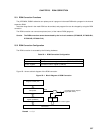
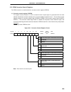
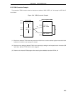
(1) Correction address registers 0 and 1 (CORAD0, CORAD1)
These registers set the start address (correction address) of the instruction(s) to be corrected in the mask
ROM.
The ROM correction corrects two places (max.) of the program. Addresses are set to two registers, CORAD0
and CORAD1. If only one place needs to be corrected, set the address to either of the registers.
CORAD0 and CORAD1 are set with a 16-bit memory manipulation instruction.
RESET input sets CORAD0 and CORAD1 to 0000H.
Figure 25-2. Correction Address Registers 0 and 1 Format
Cautions 1. Set the CORAD0 and CORAD1 when bit 1 (COREN0) and bit 3 (COREN1) of the correction
control register (CORCN : see Figure 25-3) are 0.
2. Only addresses where operation codes are stored can be set in CORAD0 and CORAD1.
3. Do not set the following addresses to CORAD0 and CORAD1.
• Address value in table area of table reference instruction (CALLT instruction) : 0040H
to 007FH
• Address value in vector table area : 0000H to 003FH
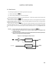
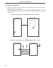
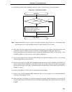
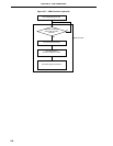
(2) Comparator
The comparator always compares the correction address value set in correction address registers 0 and 1
(CORAD0, CORAD1) with the fetch address value. When bit 1 (COREN0) or bit 3 (COREN1) of the correction
control register (CORCN) is 1 and the correction address matches the fetch address value, the correction
branch request signal (BR !F7FDH) is generated from the ROM correction circuit.