


99
CHAPTER 5 CPU ARCHITECTURE
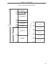
5.1.1 Internal program memory space
The internal program memory space
stores programs and table data. Normally, they are addressed with a program
counter (PC).
Each product of the
µ
PD78054 and 78054Y Subseries has the internal ROM (or PROM) of the size shown below.
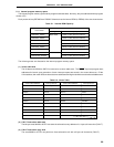
Table 5-1. Internal ROM Capacity
Part number
Internal ROM
Type Capacity
µ
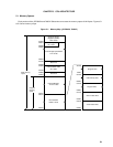
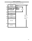
PD78052, 78052Y Mask ROM 16384 x 8 bits (0000H to 3FFFH)
µ
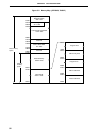
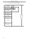
PD78053, 78053Y 24576 x 8 bits (0000H to 5FFFH)
µ
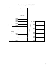
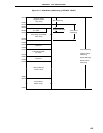
PD78054, 78054Y 32768 x 8 bits (0000H to 7FFFH)
µ
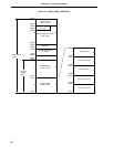
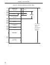
PD78055, 78055Y 40960 x 8 bits (0000H to 9FFFH)
µ
PD78056, 78056Y 49152 x 8 bits (0000H to BFFFH)
µ
PD78058, 78058Y 61440 x 8 bits (0000H to EFFFH)
µ
PD78P054 PROM 32768 x 8 bits (0000H to 7FFFH)
µ
PD78P058, 78P058Y 61440 x 8 bits (0000H to EFFFH)
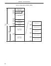
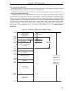
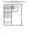
The following areas are allocated to the internal program memory space.
(1) Vector table area
The 64-byte area 0000H to 003FH is reserved as a vector table area. The RESET input and program start
addresses for branch upon generation of each interrupt request are stored in the vector table area. Of the
16-bit address, low-order 8 bits are stored at even addresses and high-order 8 bits are stored at odd addresses.
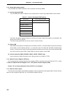
Table 5-2. Vector Table
Vector Table Address Interrupt Source Vector Table Address Interrupt Source
0000H RESET input 0018H INTSER
0004H INTWDT 001AH INTSR/INTCSI2
0006H INTP0 001CH INTST
0008H INTP1 001EH INTTM3
000AH INTP2 0020H INTTM00
000CH INTP3 0022H INTTM01
000EH INTP4 0024H INTTM1
0010H INTP5 0026H INTTM2
0012H INTP6 0028H INTAD
0014H INTCSI0 003EH BRK
0016H INTCSI1
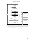
(2) CALLT instruction table area
The 64-byte area 0040H to 007FH can store the subroutine entry address of a 1-byte call instruction (CALLT).
(3) CALLF instruction entry area
The area 0800H to 0FFFH can perform a direct subroutine call with a 2-byte call instruction (CALLF).