


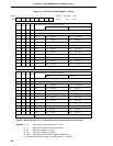

228
CHAPTER 9 8-BIT TIMER/EVENT COUNTERS 1 AND 2
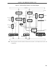
9.4 8-Bit Timer/Event Counters 1 and 2 Operations
9.4.1 8-bit timer/event counter mode
(1) Interval timer operations
The 8-bit timer/event counters 1 and 2 operate as interval timers which generate interrupt requests repeatedly
at intervals of the count value preset to 8-bit compare registers 10 and 20 (CR10 and CR20).
When the count values of the 8-bit timer registers 1 and 2 (TM1 and TM2) match the values set to CR10 and
CR20, counting continues with the TM1 and TM2 values cleared to 0 and the interrupt request signals (INTTM1
and INTTM2) are generated.
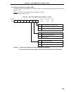
Count clock of TM1 can be selected with bits 0 to 3 (TCL10 to TCL13) of the timer clock select register 1 (TCL1).
Count clock of TM2 can be selected with bits 4 to 7 (TCL14 to TCL17) of the timer clock select register 1 (TCL1).
For the operation when the value of the compare register is changed during the timer count operation, refer
to 9.5 8-Bit Timer/Event Counter Precautions (3).
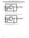
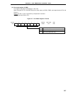
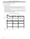
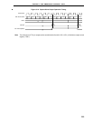
Figure 9-8. Interval Timer Operation Timings
Remark Interval time = (N + 1) × t : N = 00H to FFH
Count Clock
TM1 Count Value
INTTM1
CR10
TO1
Interval Time Interval Time Interval Time
Interrupt Request Acknowledge Interrupt Request Acknowledge
NNNN
Count Start Clear Clear
t
00 01 N 00 01 N 00 01 N