


533
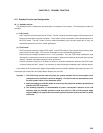
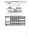
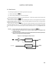
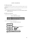
RESET
Count Clock
Reset Control Circuit
Watchdog Timer
Stop
Over-
flow
Reset
Signal
Interrupt
Function
CHAPTER 24 RESET FUNCTION
24.1 Reset Function
The following two operations are available to generate the reset signal.
(1) External reset input with RESET pin
(2) Internal reset by watchdog timer overrun time detection
External reset and internal reset have no functional differences. In both cases, program execution starts at the
address at 0000H and 0001H by RESET input.
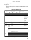
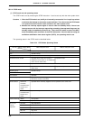
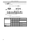
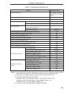
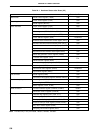
When a low level is input to the RESET pin or the watchdog timer overflows, a reset is applied and each hardware
is set to the status as shown in Table 24-1. Each pin has high impedance during reset input or during oscillation
stabilization time just after reset clear.
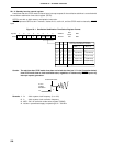
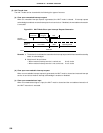
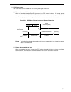
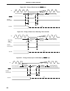
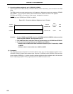
When a high level is input to the RESET input, the reset is cleared and program execution starts after the lapse
of oscillation stabilization time (2
17
/fX). The reset applied by watchdog timer overflow is automatically cleared after
a reset and program execution starts after the lapse of oscillation stabilization time (2
17
/fX) (see Figure 24-2 to 24-
4).
Cautions 1. For an external reset, input a low level for 10
µ
s or more to the RESET pin.
2. During reset input, main system clock oscillation remains stopped but subsystem clock
oscillation continues.
3. When the STOP mode is cleared by reset, the STOP mode contents are held during reset input.
However, the port pin becomes high-impedance.
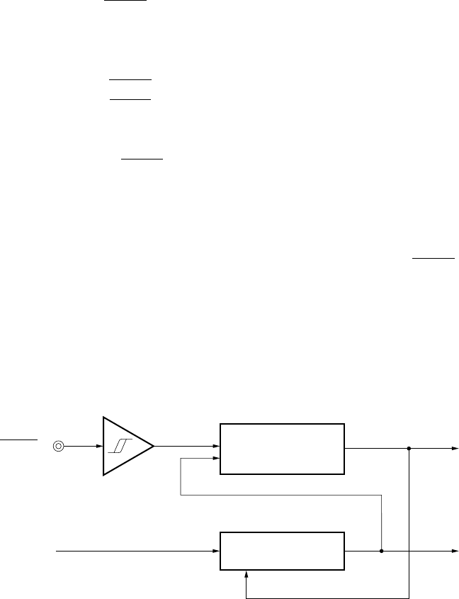
Figure 24-1. Block Diagram of Reset Function