ProSecure Unified Threat Management (UTM) Appliance Reference Manual
Using the Setup Wizard to Provision the UTM in Your Network 2-5
v1.0, January 2010
Understanding the Web Management Interface Menu Layout
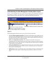
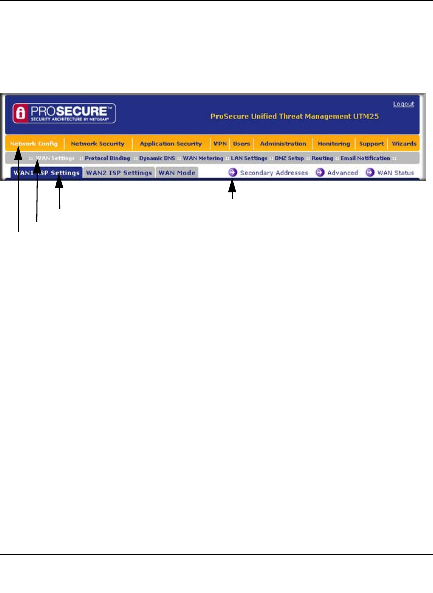
Figure 2-3 shows the menu at the top of a dual-WAN port model’s Web Management Interface (in
this example, the UTM25). The single-WAN port model’s Web Management Interface layout is
identical with the exception that it shows only a single WAN ISP Setting submenu tab.
The Web Management Interface menu consists of the following components:
• 1st Level: Main navigation menu links. The main navigation menu in the orange bar across
the top of the Web Management Interface provide access to all the configuration functions of
the UTM, and remain constant. When you select a main navigation menu link, the letters are
displayed in white against an orange background.
• 2nd Level: Configuration menu links. The configuration menu links in the gray bar
(immediately below the main navigation menu bar) change according to the main navigation
menu link that you select. When you select a configuration menu link, the letters are displayed
in white against a grey background.
• 3rd Level: Submenu tabs. Each configuration menu item has one or more submenu tabs that
are listed below the grey menu bar. When you select a submenu tab, the text is displayed in
white against a blue background.
• Option arrows. If there are additional screens for the submenu item, they are displayed on the
right side in blue letters against a white background, preceded by a white arrow in a blue
circle.
Figure 2-3
1st Level: Main Navigation Menu Link (orange)
2nd Level: Configuration Menu Link (gray)
3rd Level: Submenu Tab (blue)
Option Arrow: Additional screen for submenu item


